Which Of The Following Update Services Uses Distribution Rings To Deploy Updates In Phases?
Networking and Security in Industrial Automation Environments
Executive Summary
Industrial companies are seeking to drive operational improvements into their production systems and assets through convergence and digitization by leveraging the new paradigms in Industrial Internet of Things (IIoT) and Industry 4.0. However, these initiatives require securely connecting production environments via standard networking technologies to allow companies and their key partners access to a rich stream of new data, real-time visibility, and when needed remote access to the systems and assets in the operational environments.
New data and visibility are the key to IIoT and Industry 4.0 initiatives that unlock new business value and transformational use cases. The industrial ecosystem is seeking to continuously improve efficiency, reduce costs, and increase Overall Equipment Effectiveness (OEE) through better access to information from real time production systems in industrial areas. With a constant flow of data, industrial companies can develop more efficient ways to connect globally with suppliers, employees, and partners and to more effectively meet the needs of their customers. Securely connecting to plant systems and assets for improved access to new data is the key to enabling use cases such as predictive maintenance, real time quality detection, asset tracking, and safety enhancements.
The Cisco® Industrial Automation solution and relevant product technologies are an essential foundation to securely connect and digitize industrial and production environments to achieve these significantly improved business operation outcomes. The Cisco solution overcomes top customer barriers to digitization and Industry 4.0 including security concerns, inflexible legacy networks, and complexity. The solution provides a proven and validated blueprint for connecting Industrial Automation and Control Systems (IACS) and production assets, improving industrial security, and improving plant data access and operating reliability. Following this best practice blueprint with Cisco market-leading technologies will help decrease deployment time, decrease risk, decrease complexity, and improve overall security and operating uptime.
Figure 1 Industrial Automation Customer Objectives and Challenges
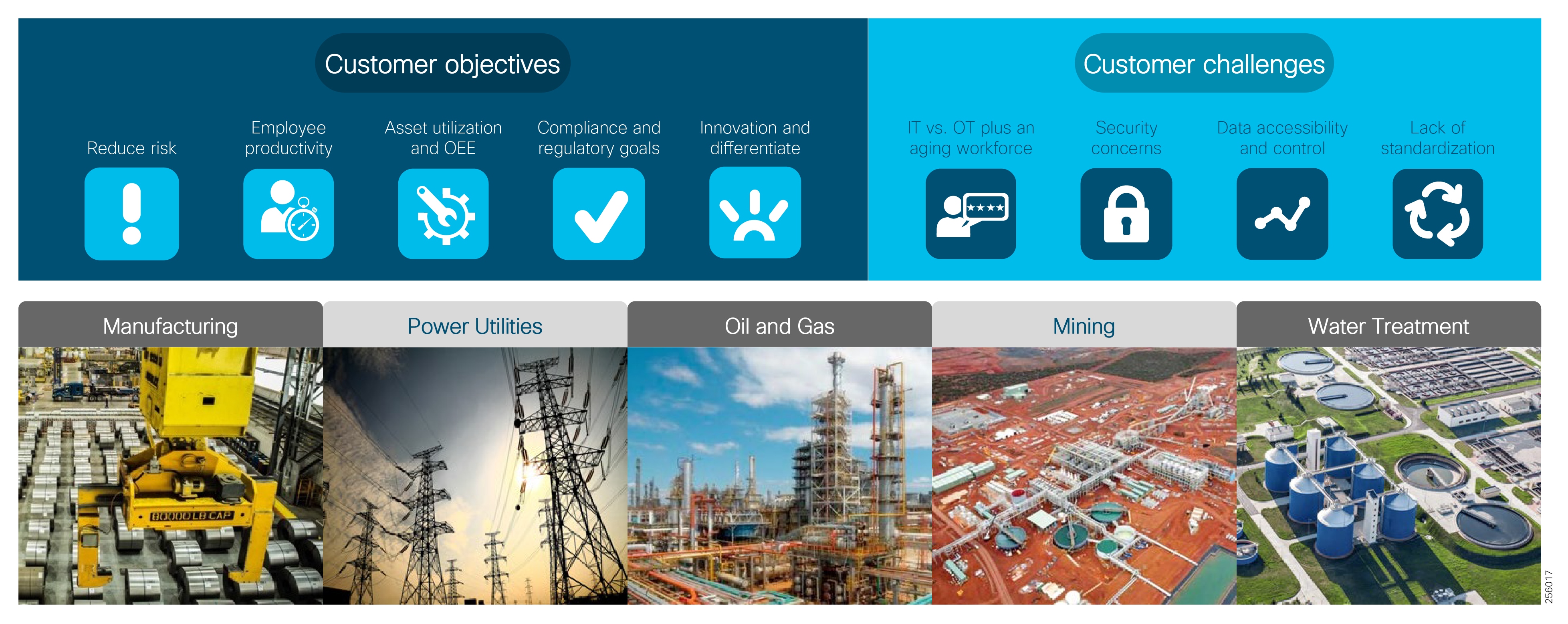
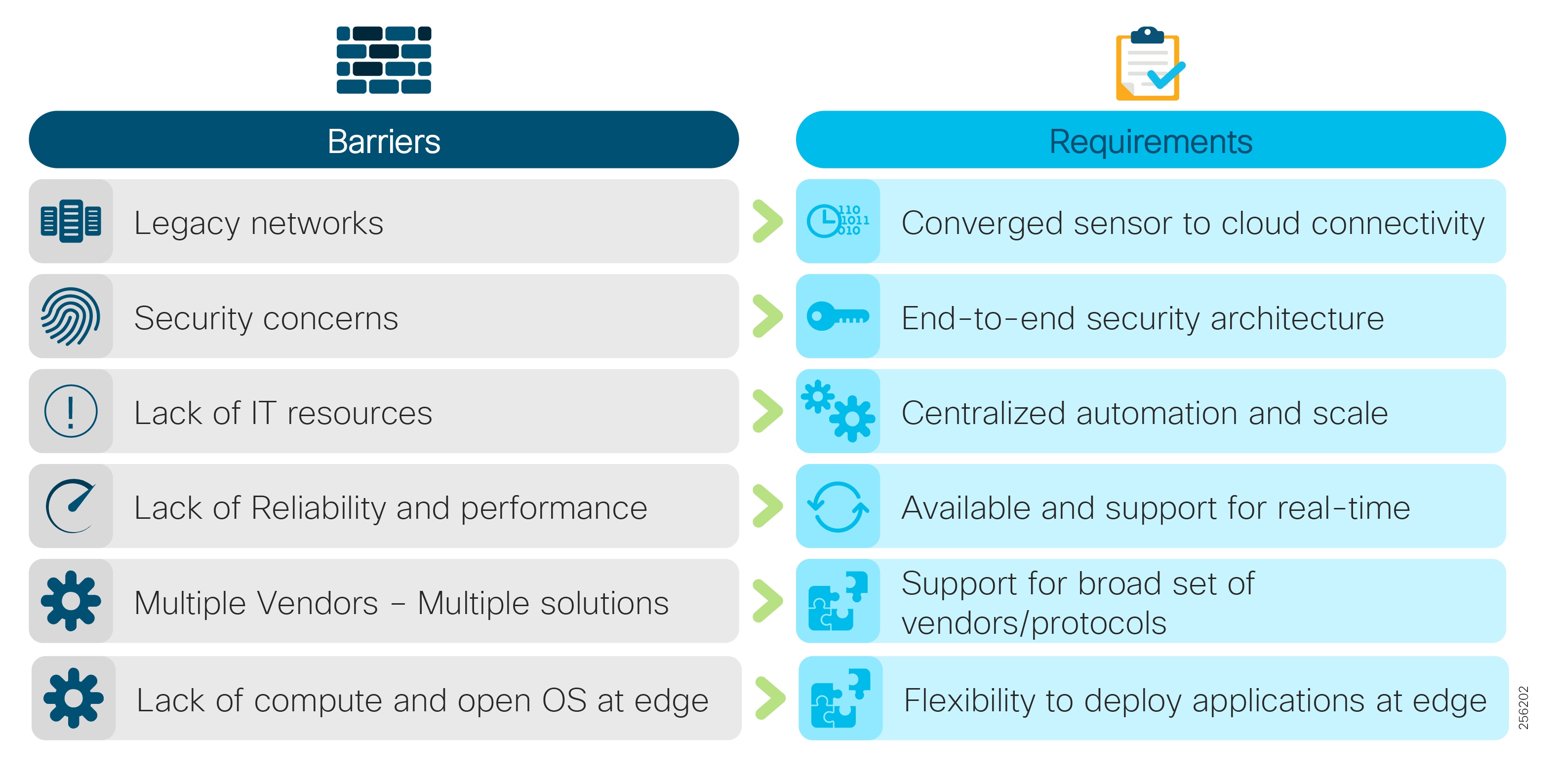
Figure 2 Why Industrial Automation Solution?
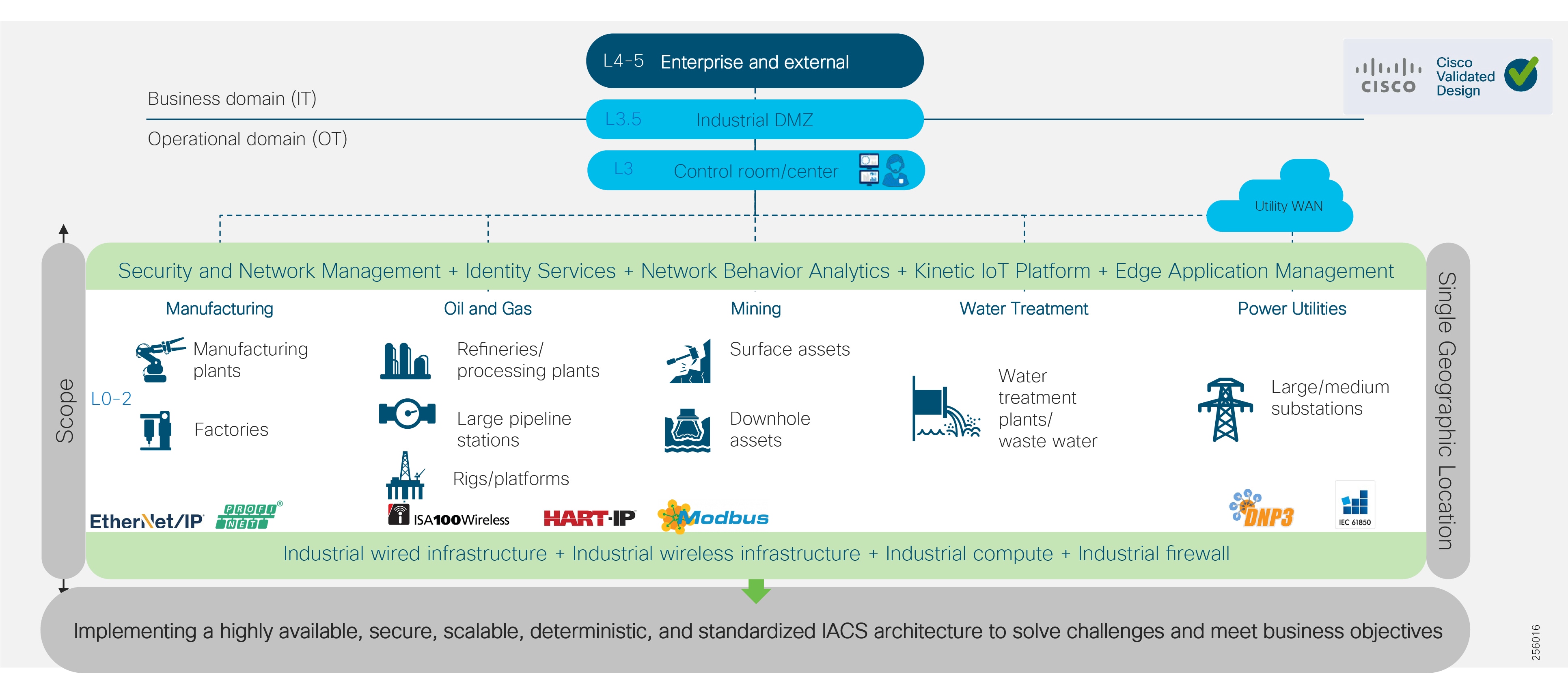
Industrial Automation Reference Architecture
The Industrial Automation Cisco Validated Design (CVD) solution applies network, security, and data management technologies to Industrial Automation and Control System (IACS) plant environments and key production assets that are the core to operational environments. It provides a Cisco validated reference architecture and design and deployment guidance for customers, partners, and system implementers. This solution is comprehensively tested with a wide range of industrial devices (for example, sensors, actuators, controllers, remote terminal units, and so on), applications, and partners. This solution's features include high-speed connectivity, scalability, high availability, ease of use, market leading industrial security, open standards, precise time distribution, and enablement of alignment and connection of information technology (IT) and operational technology (OT) environments. The solution is meant to be applied in a range of industrial verticals for secure networking of Industrial Automation systems including manufacturing, mining, oil and gas, and utility companies and for places such as plants, factories, refineries, mines, treatment facilities, substations, and warehouses.
This solution provides a blueprint for the essential security and connectivity foundation required to deploy and implement Industry 4.0 and IIoT concepts and models. This solution is thus the key to digitizing industrial and production environments to achieve significantly improved business operation outcomes.
Figure 3 Industrial Automation Reference Architecture
Cross-Industry Applicability
This Industrial Automation solution encompasses networking, security, and data management applied to a wide range of industrial verticals and applications, providing a range of design and implementation alternatives that may be applicable to several industries. Although the size, vendors, applications, and devices may significantly vary among these facilities, many of the core networking and security concepts are applicable. For example, while high availability is a key requirement across all industrial use cases, oil and gas and utilities may have more stringent availability requirements than a manufacturing facility. Nonetheless, the CVD solution best practice guidance is applicable across many industries and industrial customer environments.
Use this reference architecture for the following applications:
■![]() Connectivity of IACS devices, including sensors, actuators, and controllers; key machines; and assets such as robots, CNC machines, tools, process skids, and RTUs
Connectivity of IACS devices, including sensors, actuators, and controllers; key machines; and assets such as robots, CNC machines, tools, process skids, and RTUs
■![]() Provide OT personnel with continuous visibility into and monitoring of the network and security status of the IACS devices and communication.
Provide OT personnel with continuous visibility into and monitoring of the network and security status of the IACS devices and communication.
■![]() Enable remote access to production assets and personnel to improve uptime.
Enable remote access to production assets and personnel to improve uptime.
■![]() Support plant-wide applications such as manufacturing execution systems, Supervisory Control and Data Acquisition (SCADA), historians, and asset management.
Support plant-wide applications such as manufacturing execution systems, Supervisory Control and Data Acquisition (SCADA), historians, and asset management.
■![]() Implement relevant network services, including DNS, DHCP, Sitewide Precise Time Distribution, and authentication.
Implement relevant network services, including DNS, DHCP, Sitewide Precise Time Distribution, and authentication.
■![]() Enable IoT applications with Edge Compute such as predictive analytics and maintenance, Digital Twin, and machine learning and optimization.
Enable IoT applications with Edge Compute such as predictive analytics and maintenance, Digital Twin, and machine learning and optimization.
| | | | | | |
| | | | | | |
| Customer challenge | Access production assets and data Security risks Complex network silos creating downtime, data isolation, and vulnerabilities. Inflexible and high operating costs Expertise to manage data, networks, and security | Access production assets and data Security risks Aging infrastructure Managing and securing silo proprietary applications and networks is costly Expertise to manage data, networks, and security | Asset reliability People and asset optimization Security risks Employee safety Complex network silos creating downtime, data isolation, and vulnerabilities Inflexible networks and high operating costs Expertise to manage data, networks, and security | Asset reliability People and asset optimization Security risks Employee safety Complex network silos creating downtime, data isolation, and vulnerabilities | Rising costs of maintenance, equipment, and supplies Dealing with leakage issues, especially in drought-impacted countries Managing facilities within geographic areas with fewer personnel Remaining compliant with changing regulations |
| | | | | | |
| Cisco Industrial Automation Solution Features | High availability One solution that is interoperable across all major industrial control system protocols End-to-end connectivity for data visibility (not physically segmented) Integrated security at all levels (that works for OT and IT) Real-time, deterministic Industrial best practice designed Manageable for repair and uptime Intent-based ease of use Flexibility (modularity) | High availability One solution that is interoperable across all major industrial control system protocols End-to-end connectivity for data visibility (not physically segmented) Integrated security at all levels (that works for OT and IT) Real-time, deterministic Industrial best practice designed Manageable for repair and uptime Intent-based ease of use Flexibility (modularity) | High availability One solution that is interoperable across all major industrial control system protocols End-to-end connectivity for data visibility (not physically segmented) Integrated security at all levels (that works for OT and IT) Real-time, deterministic Industrial best practice designed Manageable for repair and uptime Intent-based ease of use Flexibility (modularity) | High availability One solution that is interoperable across all major industrial control system protocols End-to-end connectivity for data visibility (not physically segmented) Integrated security at all levels (that works for OT and IT) Real-time, deterministic Industrial best practice designed Manageable for repair and uptime Intent-based ease of use Flexibility (modularity) | High availability One solution that is interoperable across all major industrial control system protocols End-to-end connectivity for data visibility (not physically segmented) Integrated security at all levels (that works for OT and IT) Real-time, deterministic Industrial best practice designed Manageable for repair and uptime Intent-based ease of use Flexibility (modularity) |
| Customer Benefits | Reliable plant operations—higher uptime and OEE from improved data visibility Lower costs and scrap through improved real-time process visibility Lower costs from reduced OpEx– Easy to configure, upgrade, replace, and maintain Secure plant operation Less downtime | Increased operational reliability Real-Time data visibility Reduced risk from security attacks Reliable network for time-sensitive and mission-critical communications High availability Real-time visibility | Improve reliability and manage risks Reduce waste and processing Increased operational reliability Shorten turnaround times Minimize fines and penalties Improve worker safety and environmental compliance Real-time visibility Secure plant operation | OEE and availability Increased production Safety and environmental compliance Reduced OpEx—– Easy to configure, upgrade, replace, and maintain Wireless to wireline to securely connect machines and people for agility and Improved safety and productivity of staff | Secure utility information management Reduced risk from security attacks Remote monitoring High availability Reduced OpEx—– Easy to configure, upgrade, replace, and maintain Safety and environmental compliance |
Evolving Plant Environment
Over the past decade or so, the pace of change in the Industrial Automation space has clearly accelerated, driven largely by technology improvements epitomized by terms such as Industrial Internet of Things, Fog/Edge computing, Smart Factories, and Industry 4.0—the fourth revolution in industrial capabilities and digitization. This section examines some of these trends and how this solution is aligned to enable them.
Industrial Internet of Things
The Industrial Internet of Things (IIoT) is based on the idea that the growth of connected devices is more and more driven not by computers and mobile devices used by humans, but by things used in all forms of automation and in the control of the industrial ecosystem. The industrial ecosystem is moving away from fieldbus technologies based on proprietary networks for communication protocols over standard networking such as Ethernet, 802.11-based Wi-Fi, and the portfolio of IP protocols (for example, TCP and UDP). This focus on open networking standards is a foundational aspect—the devices or "things" that make up the industrial ecosystem are capable of communicating on converged, open networks, which significantly improves the accessibility of data and information. This IIoT therefore enables Digital Transformation and the revolution of the industrial ecosystem referred to as Industry 4.0. This solution, by driving converged, open networks into these industrial ecosystems establishes the IIoT for customers who adopt it.
Industry 4.0
Industry 4.0 is based on the idea that manufacturing, utilities, mining, and oil and gas are going through a fourth industrial revolution. It can be seen as the summation of industrial and computing trends. At the heart is the concept that physical devices, machines, and processes can be tightly controlled and operated significantly better by combing them with cyber-systems, IIoT, cloud computing, artificial intelligence, machine learning, and other relevant technologies.
Industry 4.0 outlines four key design principles:
■![]() Interconnection—The ability of machines, devices, sensors, and people to connect and communicate with each other via the Internet of Things (IoT).
Interconnection—The ability of machines, devices, sensors, and people to connect and communicate with each other via the Internet of Things (IoT).
■![]() Information transparency—The transparency afforded by Industry 4.0 technology provides operators with vast amounts of useful information needed to make appropriate decisions. Interconnectivity allows operators to collect immense amounts of data and information from all points in the manufacturing process, thus aiding functionality and identifying key areas that can benefit from innovation and improvement.
Information transparency—The transparency afforded by Industry 4.0 technology provides operators with vast amounts of useful information needed to make appropriate decisions. Interconnectivity allows operators to collect immense amounts of data and information from all points in the manufacturing process, thus aiding functionality and identifying key areas that can benefit from innovation and improvement.
■![]() Technical assistance—First, the ability to support humans by aggregating and visualizing information comprehensively for making informed decisions and solving urgent problems on short notice. Second, the ability of cyber physical systems to physically support humans by conducting a range of tasks that are unpleasant, too exhausting, or unsafe for their human co-workers.
Technical assistance—First, the ability to support humans by aggregating and visualizing information comprehensively for making informed decisions and solving urgent problems on short notice. Second, the ability of cyber physical systems to physically support humans by conducting a range of tasks that are unpleasant, too exhausting, or unsafe for their human co-workers.
■![]() Decentralized decisions—The ability of cyber physical systems to make decisions on their own and to perform their tasks as autonomously as possible. Only in the case of exceptions, interferences, or conflicting goals are tasks delegated to a higher level.
Decentralized decisions—The ability of cyber physical systems to make decisions on their own and to perform their tasks as autonomously as possible. Only in the case of exceptions, interferences, or conflicting goals are tasks delegated to a higher level.
The Cisco Industrial Automation solution is a foundational aspect of an Industry 4.0 approach, focusing heavily on the interconnection and cybersecurity of industrial environments, but also providing information transparency through data management capabilities, technical assistance through remote connectivity and collaboration capabilities, as well as decentralized decisions with the fog/edge computing capabilities.
Cisco Industrial Automation Solution Features
This Industrial Automation solution applies the best IT capabilities and expertise tuned and aligned with OT requirements and applications and delivers for industrial environments:
■![]() High Availability for all key industrial communication and services
High Availability for all key industrial communication and services
■![]() Real-time, deterministic application support with low network latency and jitter for the most challenging applications, such as motion control
Real-time, deterministic application support with low network latency and jitter for the most challenging applications, such as motion control
■![]() Deployable in a range of industrial environmental conditions with Industrial-grade as well as commercial-off-the-shelf (COTS) IT equipment
Deployable in a range of industrial environmental conditions with Industrial-grade as well as commercial-off-the-shelf (COTS) IT equipment
■![]() Scalable from small (tens to hundreds of IACS devices) to very large (thousands to 10,000s) deployments
Scalable from small (tens to hundreds of IACS devices) to very large (thousands to 10,000s) deployments
■![]() Intent-based manageability and ease-of-use to facilitate deployment and maintenance especially by OT personnel with limited IT capabilities and knowledge
Intent-based manageability and ease-of-use to facilitate deployment and maintenance especially by OT personnel with limited IT capabilities and knowledge
■![]() Compatible with industrial vendors, including Rockwell Automation, Schneider Electric, Siemens, Mitsubishi Electric, Emerson, Honeywell, Omron, and SEL
Compatible with industrial vendors, including Rockwell Automation, Schneider Electric, Siemens, Mitsubishi Electric, Emerson, Honeywell, Omron, and SEL
■![]() Reliance on open standards to ensure vendor choice and protection from proprietary constraints
Reliance on open standards to ensure vendor choice and protection from proprietary constraints
■![]() Distribution of Precise Time across the site to support motion applications and Schedule of Events data collection
Distribution of Precise Time across the site to support motion applications and Schedule of Events data collection
■![]() Converged network to support communication from sensor to cloud enabling many Industry 4.0 use cases
Converged network to support communication from sensor to cloud enabling many Industry 4.0 use cases
■![]() IT-preferred security architecture integrating OT context and applicable and validated for Industrial applications (achieves best practices for both OT and IT environments)
IT-preferred security architecture integrating OT context and applicable and validated for Industrial applications (achieves best practices for both OT and IT environments)
■![]() Deploy IoT application with support for Edge Compute
Deploy IoT application with support for Edge Compute
■![]() OT-focused, continuous cybersecurity monitoring of IACS devices and communications
OT-focused, continuous cybersecurity monitoring of IACS devices and communications
Solution Benefits for Industrial Environments
Benefits of securely connecting industrial automation systems via deploying this solution and the relevant Cisco technologies include:
■![]() Reduce risk in the production environment through industry-leading IT- and OT-focused security
Reduce risk in the production environment through industry-leading IT- and OT-focused security
■![]() Improve operational equipment effectiveness (OEE) and asset utilization through increased production availability and increased control system and asset visibility
Improve operational equipment effectiveness (OEE) and asset utilization through increased production availability and increased control system and asset visibility
■![]() Reduce product defects through early indication of quality impacting events or conditions
Reduce product defects through early indication of quality impacting events or conditions
■![]() Faster deployment of new lines or line modifications or new plants
Faster deployment of new lines or line modifications or new plants
■![]() Faster troubleshooting of equipment (with reduction in connectivity or security-related downtime)
Faster troubleshooting of equipment (with reduction in connectivity or security-related downtime)
What's New for Industrial Environments in this CVD?
This solution leverages and extends existing documentation and testing, as indicated in the executive summary. This version relies on that body of work and incorporates new products and technologies to further enhance the offer. Solution enhancements include:
■![]() Oil and Gas —Support for Process Control and Refinery applications with a focus on wireless support based upon the new IW6300 Intrinsically safe Wi-Fi access points backhauling wireless sensor traffic from Wireless Hart systems. This support includes support for uninterrupted service migration from legacy 1552 APs to IW6300s, including the wireless LAN controllers to manage them.
Oil and Gas —Support for Process Control and Refinery applications with a focus on wireless support based upon the new IW6300 Intrinsically safe Wi-Fi access points backhauling wireless sensor traffic from Wireless Hart systems. This support includes support for uninterrupted service migration from legacy 1552 APs to IW6300s, including the wireless LAN controllers to manage them.
■![]() Expanded support of Cisco Software-Defined Access (SDA) Ready platforms —The Cisco IE 3200, Cisco IE 3300, and Cisco IE 3400 Rugged Series switches, now including the IP67 rated Cisco IE 3400 H, have expanded support for Profinet, a range of resiliency protocols, and fully participate in the Cell/Area Zone security features.
Expanded support of Cisco Software-Defined Access (SDA) Ready platforms —The Cisco IE 3200, Cisco IE 3300, and Cisco IE 3400 Rugged Series switches, now including the IP67 rated Cisco IE 3400 H, have expanded support for Profinet, a range of resiliency protocols, and fully participate in the Cell/Area Zone security features.
■![]() Cisco Cyber Vision Industrial Cyber Security —Integrated Cisco Cyber Vision OT-focused industrial cybersecurity visibility and monitoring
Cisco Cyber Vision Industrial Cyber Security —Integrated Cisco Cyber Vision OT-focused industrial cybersecurity visibility and monitoring
Note on SDA-Ready Platforms—The Cisco Catalyst 9300 switch was introduced and validated as the distribution switch for the Cell/Area Zone. The Cisco Catalyst 9300 platform currently supports Software-Defined Access, which provides automated configuration and end-to-end segmentation to separate user, device, and application traffic without redesigning the network. SDA automates user access policy so organizations can make sure the right policies are established for any user or device with any application across the network. Ease of management and intent-driven networking with policy will be valuable additions for the industrial plant environments. Cisco is leveraging SDA in our Cisco IoT Extended Enterprise solutions for non-carpeted spaces (see www.cisco.com/go/iotcvd) where IT manages portions of industrial plants, warehouses, parking lots, roadways/intersections, etc. However, SDA is not yet validated for deployment to support industrial automation and control (the control loop) applications in the Cell/Area Zone in this solution. The new IE platforms are being positioned in the architecture to prepare for when SDA is able to support Cell/Area Zone industrial automation and control application requirements and protocols.
Intended Audience
This CVD is intended for anyone deploying IACS systems. It is intended to be used by both IT and OT personnel to drive secure convergence of industrial systems into Enterprise networks. The solution provides industrial automation network and security design and implementation guidance for vendors, partners, system implementers, customers, and service providers involved in designing, deploying, or operating production systems. This design and implementation guide provides a comprehensive explanation of the Cisco recommended networking and security for IACS. It includes information about the system architecture, possible deployment models, and guidelines for implementation and configuration. This guide also recommends best practices when deploying the validated reference architecture.
Industrial Automation Architecture Considerations
The section provides foundational concepts, building blocks, and considerations for industrial automation environments.
Plant Logical Framework
The 20th century saw a significant increase in the output of industrial processes and verticals, from utilities to process and discrete manufacturing. These developments were largely driven through automation and control technology advancements including the invention of the programmable logic controllers (PLCs), industrial robots, computerized-numeric control machines (machine tools), and the like; these paired with software-based applications, such as SCADA, Manufacturing Execution System (MES), and Historian and Asset Management systems launched IACS.
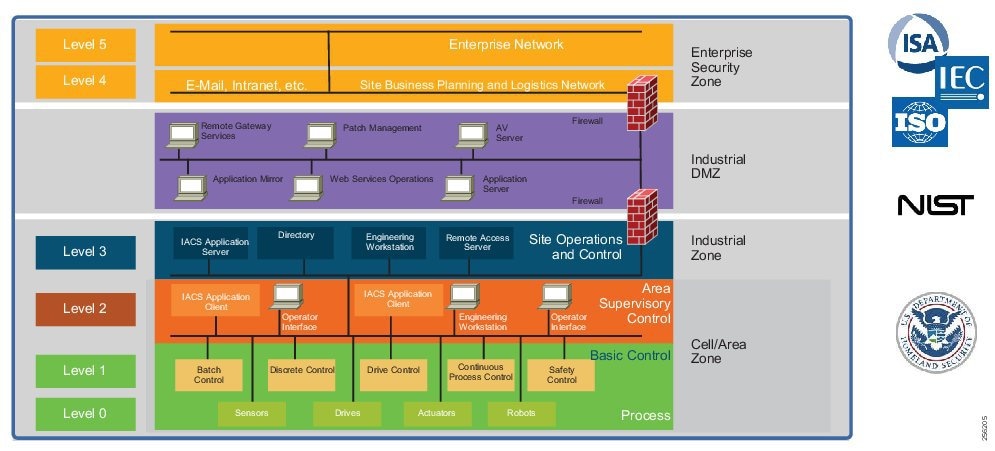
To understand the security and network systems requirements of an IACS, this guide uses a logical framework to describe the basic functions and composition of an industrial system. The Purdue Model for Control Hierarchy (reference ISBN 1-55617-265-6) is a common and well-understood model in the industry that segments devices and equipment into hierarchical functions. Based on this segmentation of IACS technology, the International Society of Automation ISA-99 Committee for Industrial and Control Systems Security and IEC 62443 Industrial Cybersecurity framework have identified the levels and logical framework shown in Figure 3. Each zone and the related levels are then subsequently described in detail in the section "Industrial Automation and Control System Reference Model" in Chapter 2 of the Converged Plantwide Ethernet (CPwE) Design and Implementation Guide :
https://www.cisco.com/c/dam/en/us/td/docs/solutions/Verticals/CPwE/CPwE-CVD-Sept-2011.pdf
Figure 4 Plant Logical Framework
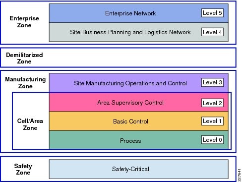
This model identifies levels of operations and defines each level. In this CVD, levels refer to this concept of levels of operations. The Open Systems Interconnection (OSI) reference model, which defines layers of network communications, is also commonly referred to when discussing network architectures. The OSI model refers to layers of network communication functions. In this CVD, unless specified, layers refer to layers of the OSI model.
Safety Zone—Safety in the Industrial Automation Control System
The need for safety is imperative in industrial environments. For example in a manufacturing environment, a robot can cause a fatal impact to personnel if proper safety procedures are not followed. Indeed, even when such procedures are followed, the robot can cause harm if it is under malicious control. Another example is Substation Automation, where the need for safety is crucial in such a high-voltage environment. As with robots in Manufacturing, a malicious actor could easily impact safety by simply engaging relays that were expected to provide isolation.
Safety in the IACS is so important that not only are safety networks isolated from (and overlaid on) the rest of the IACS, they typically have color-coded hardware and are subject to more stringent standards. In addition, Personal Protection Equipment (PPE) and physical barriers are required to promote safety. Industrial automation allows safety devices to coexist and interoperate with standard IACS devices on the same physical infrastructure, which reduces cost and improves operational efficiency.
Cell Area/Zones—Access and Control
The Cell/Area Zone is a functional area within a plant facility and many plants have multiple Cell/Area Zones. Larger plants might have "Zones" designated for fairly broad processes that have smaller subsets of "Cell Areas" within them where the process is broken down into ever smaller subsets. For example, in an automotive assembly plant, a "Zone"" might be a paint shop—where unfinished chassis arrive from the stamping plant, are painted, and then proceed on to the rest of assembly. In this case, a "Cell" within that Zone might be a Cell for priming that feeds another Cell for base color and yet another cell for top coat.
Because most networks in this area carry both non-critical traffic (for example, Historian) as well as time critical, deterministic traffic (for control loops), managed switching with strict quality of service (QoS) requirements is necessary. All switches, routers, firewalls, and so on are strictly maintained. However, unmanaged switches do exist in the machine networks (but still not routers or firewalls), but these are only possible because of the highly controlled nature of the traffic. These unmanaged switches are preferred because of their boot time speed and ease of replacement, versus a fully-managed switch equipped with troubleshooting and monitoring capabilities.
This zone has essentially three levels of activity occurring, as described in the following subsections.
Level 0—Process
Level 0 consists of a wide variety of sensors and actuators involved in the basic industrial process. These devices perform the basic functions of the IACS, such as driving a motor, measuring variables, setting an output, and performing key functions such as painting, welding, bending, and so on. These functions can be very simple (temperature gauge) to highly complex (a moving robot).
These devices take direction from and communicate status to the control devices in Level 1 of the logical model. In addition, other IACS devices or applications may need to directly access Level 0 devices to perform maintenance or resolve problems on the devices. The main attributes of Level 0 devices are:
■![]() Drive the real-time, deterministic communication requirements
Drive the real-time, deterministic communication requirements
■![]() Measure the process variables and control process outputs
Measure the process variables and control process outputs
■![]() Exist in challenging physical environments that drive topology constraints
Exist in challenging physical environments that drive topology constraints
■![]() Vary according to the size of the IACS network from a small (10s) to a large (1000s) number of devices
Vary according to the size of the IACS network from a small (10s) to a large (1000s) number of devices
■![]() Once designed and installed, are not replaced all together until the plant line is overhauled or replaced, which is typically five or more years
Once designed and installed, are not replaced all together until the plant line is overhauled or replaced, which is typically five or more years
Level 1—Basic Control
Level 1 consists of controllers that direct and manipulate the manufacturing process, primarily interfacing with the Level 0 devices (for example, I/O, sensors and actuators). In discrete environments, the controller is typically a PLC, whereas in process environments, the controller is referred to as a distributed control system (DCS). For the purposes of this solution architecture, "controllers" refers to multidiscipline controllers used across industries.
IACS controllers run industry-specific operating systems that are programmed and configured from engineering workstations. IACS controllers are modular computers that consist of some or all of the following:
■![]() A controller that computes all the data and executes programs loaded onto it
A controller that computes all the data and executes programs loaded onto it
■![]() I/O or network modules that communicate with Level 0 devices, Level 2 human-machine interfaces (HMIs), or other Level 1 controllers
I/O or network modules that communicate with Level 0 devices, Level 2 human-machine interfaces (HMIs), or other Level 1 controllers
■![]() Integrated or separate power modules that deliver power to the rest of the controller and potentially other devices
Integrated or separate power modules that deliver power to the rest of the controller and potentially other devices
IACS controllers are the intelligence of the IACS, making the basic decisions based on feedback from the devices found at Level 0. Controllers act alone or in conjunction with other controllers to manage the devices and thereby the industrial process. Controllers also communicate with other functions in the IACS (for example, Historian, asset manager, and manufacturing execution system) in Levels 2 and 3. The controller performs as a director function in the Industrial zone, translating high-level parameters (for example, recipes) into executable orders, consolidating the I/O traffic from devices, and passing the I/O data on to the upper-level plant floor functions.
Thus, controllers produce IACS network traffic in three directions from a level perspective:
■![]() Downward to the devices in Level 0 that they control and manage
Downward to the devices in Level 0 that they control and manage
■![]() Peer-to-peer to other controllers to manage the IACS for a Cell/Area Zone
Peer-to-peer to other controllers to manage the IACS for a Cell/Area Zone
■![]() Upward to HMIs and information management systems in Levels 2 and 3
Upward to HMIs and information management systems in Levels 2 and 3
Level 2—Area Supervisory Control
Level 2 represents the applications and functions associated with the Cell/Area Zone runtime supervision and operation, which include:
■![]() Operator interfaces or HMIs
Operator interfaces or HMIs
■![]() Alarms or alerting systems
Alarms or alerting systems
■![]() Control room workstations
Control room workstations
Depending on the size or structure of a plant, these functions may exist at the site level (Level 3). These applications communicate with the controllers in Level 1 and interface or share data with the site level (Level 3) or enterprise (Levels 4 to 5) systems and applications through the demilitarized zone (DMZ). These applications can be implemented on dedicated IACS vendor operator interface terminals or on standard computing equipment and operating systems such as Microsoft Windows. These applications are more likely to communicate with standard Ethernet and IP networking protocols and are typically implemented and maintained by the industrial organization.
Industrial Zone
The Industrial zone comprises the Cell/Area zones (Levels 0 to 2) and site-level (Level 3) activities. The Industrial zone is important because all the IACS applications, devices, and controllers critical to monitoring and controlling the plant floor IACS operations are in this zone. To preserve smooth plant operations and functioning of the IACS applications and IACS network in alignment with standards such as IEC 62443, this zone requires clear logical segmentation and protection from Levels 4 and 5.
Level 3—Site Operations and Control
Level 3, the site level, represents the highest level of the IACS. This space is generally "carpeted space"-meaning it has HVAC with typical 19-inch rack-mounted equipment in hot/cold aisles utilizing commercial grade equipment.
As the name implies, this is where applications related to operating the site reside, where operating the site means the applications and services that are directly driving production. For example, what is generally not included at this level are the more enterprise-centric applications such as Engineering Resource Planning (ERP) systems or Manufacturing Execution Systems (MES), as those applications tend to be more business management applications and therefore more closely aligned and integrated with enterprise applications. Examples of services at this level would be Historians, control applications, network and IACS management software, and network security services. Control applications will vary greatly on the specifics of the plant. An example from an automotive assembly plant would be for a Paint Coordination application that might be directly controlling chassis coming from the Stamping Plant fed to Robotic Paint Controllers in the Paint zone. The Level 1 controllers (the Robotic Controller in this example) would often be ruggedized, require determinism for their control loops, and be at or near the actual operations. In contrast, the Paint Coordination applications at the Site level are not true control loop applications and can reside in carpeted space.
The systems and applications that exist at this level manage plantwide IACS functions. Levels 0 through 3 are considered critical to site operations. The applications and functions that exist at this level include the following:
■![]() Level 3 IACS network
Level 3 IACS network
■![]() Reporting (for example: cycle times, quality index, predictive maintenance)
Reporting (for example: cycle times, quality index, predictive maintenance)
■![]() Plant historian
Plant historian
■![]() Detailed production scheduling
Detailed production scheduling
■![]() Site-level operations management
Site-level operations management
■![]() Asset and material management
Asset and material management
■![]() Control room workstations
Control room workstations
■![]() Patch launch server
Patch launch server
■![]() File server
File server
■![]() Other domain services, for example Active Directory (AD), DHCP, Domain Name System (DNS), Windows Internet Naming Service (WINS), Network Time Protocol (NTP), Precision Time Protocol Grandmaster Clock, and so on
Other domain services, for example Active Directory (AD), DHCP, Domain Name System (DNS), Windows Internet Naming Service (WINS), Network Time Protocol (NTP), Precision Time Protocol Grandmaster Clock, and so on
■![]() Terminal server for remote access support
Terminal server for remote access support
■![]() Staging area
Staging area
■![]() Administration and control applications
Administration and control applications
The Level 3 IACS network may communicate with Level 1 controllers and Level 0 devices, function as a staging area for changes into the Industrial zone, and share data with the enterprise (Levels 4 and 5) systems and applications through the DMZ. These applications are primarily based on standard computing equipment and operating systems (Unix-based or Microsoft Windows). For this reason, these systems are more likely to communicate with standard Ethernet and IP networking protocols.
Additionally, because these systems tend to be more aligned with standard IT technologies, they may also be implemented and supported by personnel with IT skill sets.
Enterprise Zone
Level 4—Site Business Planning and Logistics
Level 4 is where the functions and systems that need standard access to services provided by the enterprise network reside. This level is viewed as an extension of the enterprise network. The basic business administration tasks are performed here and rely on standard IT services. These functions and systems include wired and wireless access to enterprise network services such as the following:
■![]() Access to the Internet and email (hosted in data centers)
Access to the Internet and email (hosted in data centers)
■![]() Non-critical plant systems such as manufacturing execution systems and overall plant reporting such as inventory, performance, and so on
Non-critical plant systems such as manufacturing execution systems and overall plant reporting such as inventory, performance, and so on
■![]() Access to enterprise applications such as SAP and Oracle (hosted in data centers)
Access to enterprise applications such as SAP and Oracle (hosted in data centers)
Although important, these services are not viewed as critical to the IACS and thus the plant floor operations. Because of the more open nature of the systems and applications within the enterprise network, this level is often viewed as a source of threats and disruptions to the IACS network.
The users and systems in Level 4 often require summarized data and information from the lower levels of the IACS network. The network traffic and patterns here are typical of a branch or campus network found in general enterprises where approximately 90 percent of the network traffic goes to the Internet or to data center applications.
This level is typically under the management and control of the IT organization.
Level 5—Enterprise
Level 5 is where the centralized IT systems and functions exist. Enterprise resource management, business-to-business, and business-to-customer services typically reside at this level. Often the external partner or guest access systems exist here, although it is not uncommon to find them in lower levels (Level 3) of the framework to gain flexibility that may be difficult to achieve at the enterprise level. However, this approach may lead to significant security risks if not implemented within IT security policy and standards.
The IACS must communicate with the enterprise applications to exchange manufacturing and resource data. Direct access to the IACS is typically not required. One exception to this would be remote access for management of the IACS by employees or partners such as system integrators and machine builders. Access to data and the IACS network must be managed and controlled through the DMZ to maintain the security, availability, and stability of the IACS.
The services, systems, and applications at this level are directly managed and operated by the IT organization.
Industrial DMZ
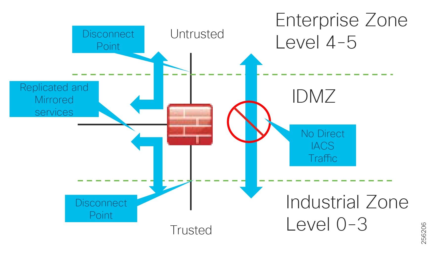
Although not part of Purdue reference model, the industrial automation solution includes a DMZ between the Industrial and Enterprise zones. The industrial DMZ is deployed within plant environments to separate the enterprise networks and the operational domain of the plant environment. Downtime in the IACS network can be costly and have a severe impact on revenue, so the operational zone cannot be impacted by any outside influences. Network access is not permitted directly between the enterprise and the plant, however, data and services are required to be shared between the zones, thus the industrial DMZ provides architecture for the secure transport of data. Typical services deployed in the DMZ include remote access servers and mirrored services. Further details on the design recommendations for the industrial DMZ can be found later in this guide.
As with IT network DMZs, the industrial DMZ is there to primarily be a buffer between the plant floor and the Enterprise or the Internet-placing the most vulnerable services, such as email, web, and DNS servers, in this isolated network. The industrial DMZ not only isolates the factory from the outside world, but also from its own enterprise networks. The primary reason this additional isolation is recommended is that, unlike enterprise services, the plant floor contains the most critical services of the company-the services that produce the very product the company sells. Often applications on the plant floor are antiquated, running on vulnerable operating systems such as Windows 95. The industrial DMZ provides another level of security for these vulnerable systems.
Another key use of the industrial DMZ is for remote access, aiding troubleshooting of production equipment affecting the company product and therefore revenue. The risk of external access compounded with antiquated equipment underscores the need for some additional security measures. The details as to how the industrial DMZ is used for such services are described in later sections.
Figure 5 Industrial Plant Reference Architecture with IDMZ
IACS Requirements and Considerations
Operational Technology Application Requirements
OT applications at their core are focused on maintaining stability, continuity, and integrity of industrial processes. At the core is a loop of sensors, controllers, and actuators that must be maintained to properly operate the industrial processes. Additionally, a number of other applications need to gather information to display status, maintain history, and optimize the industrial process operations. From this standpoint, this solution outlines how to achieve a set of key requirements to support the OT applications, including:
■![]() High availability as applications often have to run 24 hours a day, 365 days a year
High availability as applications often have to run 24 hours a day, 365 days a year
■![]() Focus on local, real-time communication between IACS devices requiring low latency and jitter in the communication to maintain the control loop integrity
Focus on local, real-time communication between IACS devices requiring low latency and jitter in the communication to maintain the control loop integrity
■![]() Ability to access diagnostic and telemetry information from IACS devices for IoT-based applications
Ability to access diagnostic and telemetry information from IACS devices for IoT-based applications
■![]() Challenge to update or change devices, software, or update configurations as the processes often run for extended periods of time
Challenge to update or change devices, software, or update configurations as the processes often run for extended periods of time
■![]() Deployable in a range of industrial environmental conditions with industrial-grade as well as COTS IT equipment when applicable
Deployable in a range of industrial environmental conditions with industrial-grade as well as COTS IT equipment when applicable
■![]() Scalable from small (tens to hundreds of IACS devices) to very large (thousands to 10,000s) deployments
Scalable from small (tens to hundreds of IACS devices) to very large (thousands to 10,000s) deployments
■![]() Access to precise time for challenging applications such as Motion Control and Sequence of Events
Access to precise time for challenging applications such as Motion Control and Sequence of Events
■![]() Simple and easy to use to management tools to facilitate deployment and maintenance, especially by OT personnel with limited IT capabilities and knowledge
Simple and easy to use to management tools to facilitate deployment and maintenance, especially by OT personnel with limited IT capabilities and knowledge
■![]() Use of open standards to ensure vendor choice and protection from proprietary constraints
Use of open standards to ensure vendor choice and protection from proprietary constraints
Ruggedization and Environmental Requirements
Typical enterprise network devices reside in controlled environments, which is a key differentiator of the IACS from typical enterprise applications. The IACS end devices and network infrastructure are located in harsh environments that require compliance to environmental specifications such as IEC 529 (ingress protection) or National Electrical Manufacturers Association (NEMA) specifications. The IACS end devices and network infrastructure may be located in physically disparate locations and in non-controlled or even harsh environmental conditions such as temperature, humidity, vibration, noise, explosiveness, or electronic interference.
Due to these environmental considerations the IACS devices and network infrastructure must support and withstand these harsh conditions. Also DIN rail compliant form factor is ideal for industrial environments when compared to enterprise which typically reside in 19-inch rack mounts.
Performance in the Industrial Automation Control System
Performance is an important consideration for design of the network. Networking engineers in general have dealt with both latency and jitter for many years, especially in VoIP networks. However, in industrial automation networks, especially as the networking gets closer to the lower Purdue levels (ANSI/ISA 951/Purdue2 Level 0-1, machines, relays), the requirements for both latency and jitter become orders of magnitude more stringent than VoIP networks. Industrial automation network equipment is very demanding and some of these devices have limited software and processing capabilities, which makes them susceptible to network-related disruptions or extraneous communication. In addition, a very quickly changing manufacturing process (for example, a paper mill) or complex automation (for example, a multi-axis robot) demand very high levels of determinism-predictable inter-packet delay in the IACS. A lack of determinism in a network can fail and shut down an industrial process causing downtime which impacts the business. To support the level of determinism needed for industrial automation networks, the following must be considered:
■![]() Marking the applications that need real-time traffic with high priority
Marking the applications that need real-time traffic with high priority
■![]() Creating a QoS policy that guarantees an appropriate bandwidth for the high priority traffic
Creating a QoS policy that guarantees an appropriate bandwidth for the high priority traffic
■![]() Planning an appropriate bandwidth on the network links
Planning an appropriate bandwidth on the network links
Availability is the most important aspect of IACS networks. This highlights another key difference with other non-industrial networking; while most IT networks have become more and more "business critical" over the years, they are generally not at the core of the business, but rather part of a service organization. In contrast, OT networking is business critical in that it is part of what the company actually does; when critical parts of the OT network go down, production stops and revenue is impacted. Note that some parts of the IACS network are more critical than others and therefore have higher availability requirements. Such criticality is ultimately translated into availability or Service Level Agreement (SLA) requirements, much of which can be seen in various parts of this CVD, but most notably in sections describing various ways of increasing availability such as sections describing resiliency protocols.
To achieve availability:
■![]() No single point of failure for IACS network infrastructure. For example: redundant links, switches, Layer 3 devices, and firewalls.
No single point of failure for IACS network infrastructure. For example: redundant links, switches, Layer 3 devices, and firewalls.
■![]() Implement network resiliency and convergence protocols which meet the IACS application requirements.
Implement network resiliency and convergence protocols which meet the IACS application requirements.
■![]() Quick and easy zero-touch replacement of network devices in industrial environments.
Quick and easy zero-touch replacement of network devices in industrial environments.
Security
The traditional approach of security deployed in Industrial automation is "security by obscurity", which is to have a very closed air-gap environment and implement proprietary protocols with no public access. The need for physical security can easily be seen in not only the examples above, but in real world examples such as Stuxnet ( https://en.wikipedia.org/wiki/Stuxnet). Stuxnet demonstrated that "security by obscurity" and even "air-gapping" are insufficient security measures (more on those topics later). In addition to the Stuxnet example, the need for physical security can be seen with more generic "man-in-the-middle" attacks or simple "network taps", where physical devices are inserted into the network. This intersection of physical and cybersecurity is generally a component of all industrial automation networks. The proprietary protocols were seen as being difficult to compromise and security incidents were more likely to be accidental. However, over the course of the last few years the industrial ecosystem has moved away from the use of proprietary network technologies to the use of open, standard networking such as Ethernet, WiFi, IP, and so on.
This approach of adding obscurity as a way of securing the networks does not meet the requirements of the current trends in industrial automation because:
■![]() Proliferation of many devices in the plant floor-First, plant networks are increasingly using COTS technology products to perform operational tasks, replacing devices that were built from the ground up specifically for the process control environment. Second, many sensors are added to the plant floor as part of big data and analytics, primarily to derive the data from the machines which can be used to enhance the productivity of the plant floor and also as a means to perform preventive maintenance on the equipment. These new devices support standard protocols and also may need access to certain resources such as cloud and internet.
Proliferation of many devices in the plant floor-First, plant networks are increasingly using COTS technology products to perform operational tasks, replacing devices that were built from the ground up specifically for the process control environment. Second, many sensors are added to the plant floor as part of big data and analytics, primarily to derive the data from the machines which can be used to enhance the productivity of the plant floor and also as a means to perform preventive maintenance on the equipment. These new devices support standard protocols and also may need access to certain resources such as cloud and internet.
■![]() Convergence of IT and OT-Organizationally, IT and OT teams and tools, which were historically separate, have begun to converge, leading to more traditionally IT-centric solutions being introduced to support operational activities. As the borders between traditionally separate OT and IT domains blur, they must align strategies and work more closely together to ensure end-to-end security.
Convergence of IT and OT-Organizationally, IT and OT teams and tools, which were historically separate, have begun to converge, leading to more traditionally IT-centric solutions being introduced to support operational activities. As the borders between traditionally separate OT and IT domains blur, they must align strategies and work more closely together to ensure end-to-end security.
Security Characteristics
With these trends in the manufacturer networks, the following fundamental principles must be adopted by the plant network operator to ensure secure systems:
■![]() Visibility of all devices in the plant network-Traditionally, enterprise devices such as laptops, mobile phones, printers, and scanners were identified by the enterprise management systems when these devices accessed the network. This visibility must be extended to all devices on the plant floor.
Visibility of all devices in the plant network-Traditionally, enterprise devices such as laptops, mobile phones, printers, and scanners were identified by the enterprise management systems when these devices accessed the network. This visibility must be extended to all devices on the plant floor.
■![]() Segmentation and zoning of the network-Segmentation is a process of bounding the reachability of a device and zoning is defining a layer where all the members in that zone will have identical security functions. Providing zones in a network provides an organized way of managing access within and across the zone. Segmenting the devices further reduces the risk of spread of an infection when a device gets subjected to malware.
Segmentation and zoning of the network-Segmentation is a process of bounding the reachability of a device and zoning is defining a layer where all the members in that zone will have identical security functions. Providing zones in a network provides an organized way of managing access within and across the zone. Segmenting the devices further reduces the risk of spread of an infection when a device gets subjected to malware.
■![]() Identification and restricted data flow-All the devices in the plant floor-enterprise (IT-managed) and operations (OT-managed)-must be identified, authenticated, and authorized and the network must enforce a policy when the users and IACS assets attach to the network.
Identification and restricted data flow-All the devices in the plant floor-enterprise (IT-managed) and operations (OT-managed)-must be identified, authenticated, and authorized and the network must enforce a policy when the users and IACS assets attach to the network.
■![]() Network anomalies-Any unusual behavior in network activity must be detected and examined to determine if the change is intended or due to a malfunction of the device. Detecting network anomalies as soon as possible gives plant operations the means to remediate an abnormality in the network sooner, which can help to reduce possible downtimes.
Network anomalies-Any unusual behavior in network activity must be detected and examined to determine if the change is intended or due to a malfunction of the device. Detecting network anomalies as soon as possible gives plant operations the means to remediate an abnormality in the network sooner, which can help to reduce possible downtimes.
■![]() Malware detection and mitigation-The unusual behavior displayed by an infected device must be detected immediately and the security tools should allow a remediate action to the infected device.
Malware detection and mitigation-The unusual behavior displayed by an infected device must be detected immediately and the security tools should allow a remediate action to the infected device.
■![]() Traditional firewalls are not typically built for industrial environments. There is a need for an industrial firewall which can perform deep packet inspection on industrial protocols to identify anomalies in IACS traffic flow.
Traditional firewalls are not typically built for industrial environments. There is a need for an industrial firewall which can perform deep packet inspection on industrial protocols to identify anomalies in IACS traffic flow.
■![]() Hardening of the networking assets and infrastructure in the plant floor is a critical consideration. This includes securing key management and control protocols such as Simple Network Management Protocols (SNMP) among others.
Hardening of the networking assets and infrastructure in the plant floor is a critical consideration. This includes securing key management and control protocols such as Simple Network Management Protocols (SNMP) among others.
■![]() Automation and Control protocols—It is also important to monitor the IACS protocols themselves for anomalies and abuse.
Automation and Control protocols—It is also important to monitor the IACS protocols themselves for anomalies and abuse.
■![]() Adhering to the security standards-In the 1990s, the Purdue Reference Model and ISA 95 created a strong emphasis on architecture using segmented levels between various parts of the control system. This was further developed in ISA99 and IEC 62443, which brought focus to risk assessment and process. The security risk assessment will identify which PMSs are defined as critical control systems, non-critical control systems, and non-control systems.
Adhering to the security standards-In the 1990s, the Purdue Reference Model and ISA 95 created a strong emphasis on architecture using segmented levels between various parts of the control system. This was further developed in ISA99 and IEC 62443, which brought focus to risk assessment and process. The security risk assessment will identify which PMSs are defined as critical control systems, non-critical control systems, and non-control systems.
Information Technology and Operational Technology Convergence
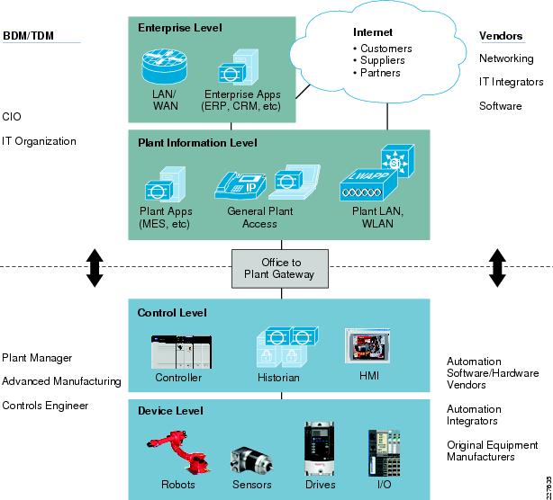
Historically, production environments and the IACS in them have been the sole responsibility of the operational organizations within enterprises. Enterprise applications and networks have been the sole responsibility of IT organizations. But as OT has started adopting standard networking, there has been a need to not only interconnect these environments, but to converge organizational capabilities and drive collaboration between vendors and suppliers.
Decisions impacting IACS networks are typically driven by plant managers and control engineers, rather than the IT department. Additionally, the IACS vendor and support supply chain are different than those typically used by the IT department. That being said, the IT departments of manufacturers are increasingly engaging with plant managers and control engineers to leverage the knowledge and expertise in standard networking technologies for the benefit of plant operations.
Figure 6 Business and Technical Decision Makers—IT and OT
Cross-Industry Industrial Networking Requirements
Table 2 summarizes cross-industry industrial network requirements, challenges, and Industrial Automation Solution features to help customers achieve various business outcomes.
| | | | |
| | | | |
| | | | |
| | | | |
| | | |
| | | | |
| | | | |
| | | | |
| | | |
Industry Standards and Regulations
Standards and guidelines are an essential foundation, but they do not prescribe how to secure and design specific systems. As all systems are different, standards and guidelines should be leveraged as a best practice framework and specifically tailored to business needs. In this section, a few of the industry standards are briefly described and limited to those that are both generally applicable and generally applied.
ISA-95/PERA (Purdue)
ISA-95 and PERA provide a general architecture for all types of IACS, providing not only common nomenclature but also common building blocks. More details can be found at:
■![]() ISA-95 web site
ISA-95 web site
https://isa-95.com/
■![]() PERA web site
PERA web site
http://www.pera.net/
IEC 62443/ISA-99
The IEC 62443 series builds on established standards for the security of general-purpose IT systems (for example, the ISO/IEC 27000 series), identifying and addressing the important differences present in an industrial control system (ICS). Many of these differences are based on the reality that cybersecurity risks within an ICS may have Health, Safety, or Environment (HSE) implications and that the response should be integrated with other existing risk management practices addressing these risks.
NIST Cybersecurity Framework
The National Institute of Standards and Technology (NIST) Cybersecurity Framework ( https://www.nist.gov/cyberframework) is a Best Practices guideline, not a requirements standard, the genesis of which came from the 2014 changes to the NIST National Institute of Standards and Technology Act, which was amended to add "...on an ongoing basis, facilitate and support the development of a voluntary, consensus-based, industry-led set of standards, guidelines, best practices, methodologies, procedures, and processes to cost-effectively reduce cyber risks to critical infrastructure."
NIST 800 Series
The NIST 800 Series, as it is commonly called, is a set of documents from NIST covering U.S. government security policies, procedures, and guidelines. Although NIST is a U.S. government unit (under the Commerce Department), these guidelines are referenced and indeed mandated by not only the U.S. but many governments and corporations around the world-even those not directly involved in the public sector. In particular to this CVD and the associated CVDs, the subset called NIST SP 800-82 "Guide to Industrial Control Systems Security" is of particular importance as it is specifically targeted at the IACS space. The purpose of this document is to provide guidance for securing ICS, including SCADA systems, DCS, and other systems performing control functions. The document provides a notional overview of ICS, reviews typical system topologies and architectures, identifies known threats and vulnerabilities to these systems, and provides recommended security countermeasures to mitigate the associated risks. Additionally, it presents an ICS-tailored security control overlay, based on NIST SP 800-53 Rev. 4 [22], to provide a customization of controls as they apply to the unique characteristics of the ICS domain.
NERC CIP
NERC CIP, or more properly the "North American Electric Reliability Corporation (NERC) Critical Infrastructure Protection (CIP)", as the name implies, is utility specific in origin, however it is widely referenced and adopted outside of the utility space. Also as its name implies, it targets "Critical Infrastructure Protection", which is a widely used term and the subject of many standards, guidelines, and best practices (see https://en.wikipedia.org/wiki/Critical_infrastructure_protection for more details). NERC CIP in particular is used in this CVD and the associated CVDs primarily because it was developed around the particulars of the IACS infrastructure (and is therefore more highly relevant to the subject and hand as well utilizing much of the same terminology).
IEEE 1588 Precise Time Protocol
Defined in IEEE1588 as Precision Clock Synchronization for Networked Measurements and Control Systems, it was developed to synchronize the clocks in packet-based networks that include distributed device clocks of varying precision and stability. Precise Time Protocol (PTP) is designed specifically for industrial, networked measurement and control systems, and is optimal for use in distributed systems because it requires minimal bandwidth and little processing overhead. PTP facilitate services which requires extremely precise time accuracy and stability like peak-hour billing, virtual power generators, outage monitoring and management, and so on.
PTP was originally developed in 2002. It was enhanced in 2008 (IEEE 1588-2008) and is referred to as PTPv2. This version establishes the basic concept and algorithms for distribution of precise time. These basics have been adopted into "profiles" that are specific definitions for distribution of time designed for particular use cases. The following PTP Profiles are:
■![]() Default Profile—This profile was defined by the IEEE 1588 working group. It has been adopted in many industrial applications, including the ODVA, Inc. Common Industrial Profile (CIP) as CIP Sync services. This solution supports the default profile in the Sitewide Precise Time Distribution feature. As well, the Rockwell Automation and Cisco Converged Plantwide Ethernet (CPwE) solution supports the default profile in the Deploying Scalable Time Distribution within a Converged Plantwide Ethernet Architecture ( https://www.cisco.com/c/en/us/td/docs/solutions/Verticals/CPwE/5-1/STD/DIG/CPwE-5-1-STD-DIG.html).
Default Profile—This profile was defined by the IEEE 1588 working group. It has been adopted in many industrial applications, including the ODVA, Inc. Common Industrial Profile (CIP) as CIP Sync services. This solution supports the default profile in the Sitewide Precise Time Distribution feature. As well, the Rockwell Automation and Cisco Converged Plantwide Ethernet (CPwE) solution supports the default profile in the Deploying Scalable Time Distribution within a Converged Plantwide Ethernet Architecture ( https://www.cisco.com/c/en/us/td/docs/solutions/Verticals/CPwE/5-1/STD/DIG/CPwE-5-1-STD-DIG.html).
■![]() Power Profile—This profile was defined by the International Electrotechnical Commission (IEC) standard 62439. The power profile is used in the IEC 61850 standard for communication protocol for substation automation. This profile is supported in the Cisco Substation Automation Local Area Network and Security CVD ( https://www.cisco.com/c/en/us/td/docs/solutions/Verticals/Utilities/SA/2-3-2/CU-2-3-2-DIG.html).
Power Profile—This profile was defined by the International Electrotechnical Commission (IEC) standard 62439. The power profile is used in the IEC 61850 standard for communication protocol for substation automation. This profile is supported in the Cisco Substation Automation Local Area Network and Security CVD ( https://www.cisco.com/c/en/us/td/docs/solutions/Verticals/Utilities/SA/2-3-2/CU-2-3-2-DIG.html).
■![]() Telecom Profile—The International Telecommunication Union's Telecommunications Standards (ITU-T) group has established a set of PTP profiles for the telecoms industries. A variety of Cisco products support these profiles, but are not commonly used in industrial automation. This profile is not supported in this solution.
Telecom Profile—The International Telecommunication Union's Telecommunications Standards (ITU-T) group has established a set of PTP profiles for the telecoms industries. A variety of Cisco products support these profiles, but are not commonly used in industrial automation. This profile is not supported in this solution.
■![]() IEEE 802.1 AS profile—The IEEE created the Timing and Synchronization for Time-Sensitive Applications at this profile as part of the Audio-Visual Bridging (AVB) set of technical standards. This profile is being enhanced for the industrial ecosystem driven Time-Sensitive Networks set of technical standards under the IEEE 802.1AS-Rev working group. Some Cisco products support 802.1AS for AVB and TSN applications. This solution does not support 802.1AS at this time.
IEEE 802.1 AS profile—The IEEE created the Timing and Synchronization for Time-Sensitive Applications at this profile as part of the Audio-Visual Bridging (AVB) set of technical standards. This profile is being enhanced for the industrial ecosystem driven Time-Sensitive Networks set of technical standards under the IEEE 802.1AS-Rev working group. Some Cisco products support 802.1AS for AVB and TSN applications. This solution does not support 802.1AS at this time.
Industrial Automation Network Model and IACS Reference Architecture
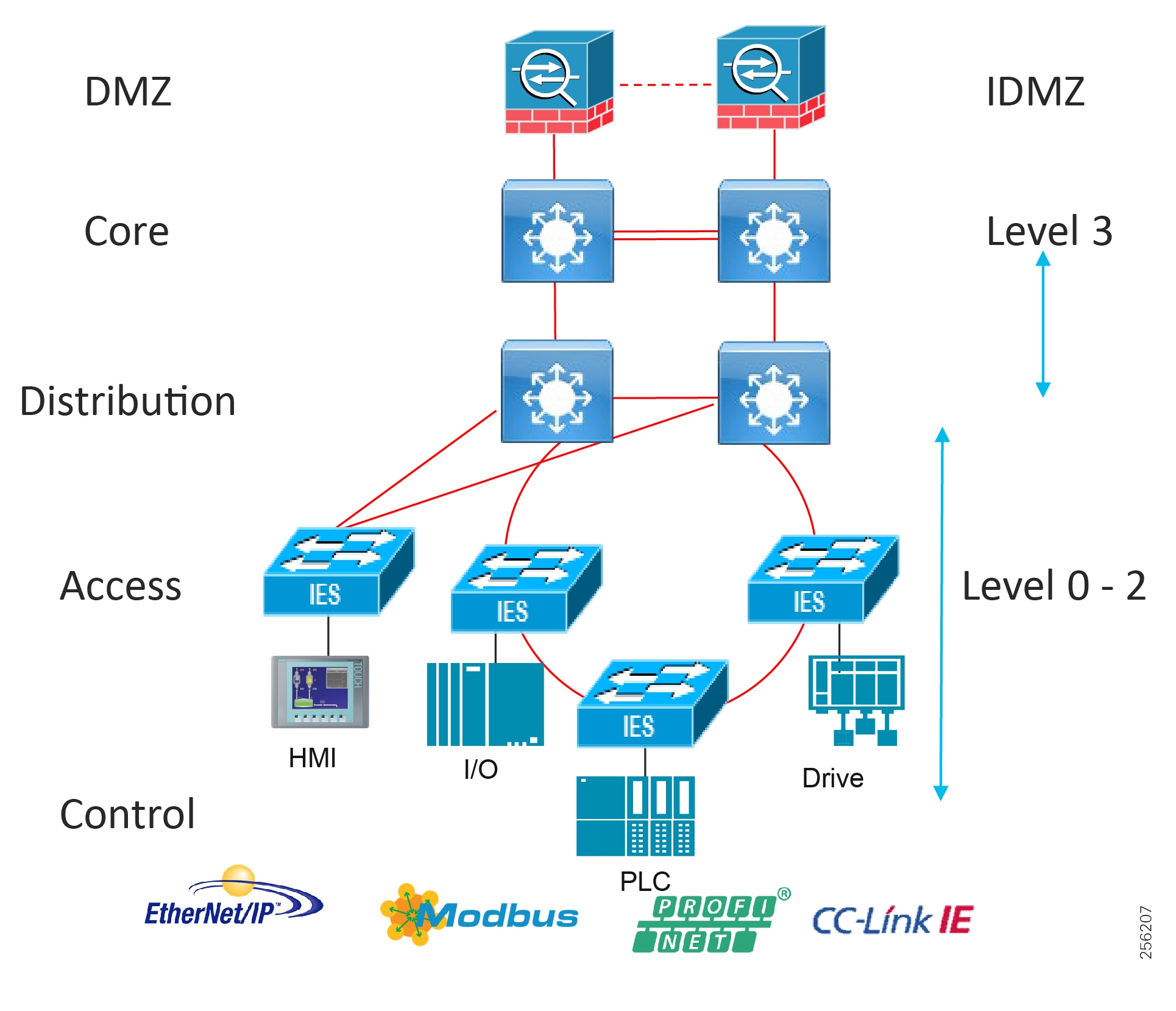
The typical enterprise campus network design is ideal for providing resilient, highly scalable, and secure connectivity for all network assets. The campus model is a proven hierarchal design that consists of three main layers: core, distribution, and access. The DMZ layer is added to provide a security interface outside of the operational plant domain. The following section maps the enterprise campus model to the IACS reference model.
Aligning the Cisco Enterprise Networking Model for the Industrial Plant
DMZ and Industrial DMZ—Level 3.5
The DMZ in the campus model typically provides an interface and restricts access into the enterprises network assets and services from the internet. The Industrial DMZ is deployed within our plant environments to separate the enterprise networks and the operational domain of the plant environment. Downtime in the IACS network can be costly and have a severe impact on revenue, therefore the operational zone cannot be impacted by any outside influences, as availability of the IACS assets and processes are paramount. Therefore network access is not permitted directly between the enterprise and the plant, however data and services are required to be shared between the operational domain and the enterprise, therefore a secure architecture for the industrial DMZ to provide secure traversal of data between the zones is required. Typical services deployed in the DMZ include Remote access servers and Mirrored services. Further details on the design recommendations for the industrial DMZ can be found later in this guide.
Figure 7 Industrial DMZ Functional Model
Core Network
The core is designed to be highly reliable and stable to aggregate all the elements in the operational plant, typically Layer 3 devices, with high speed connectivity, redundant links, and redundant hardware. Within the context of the plant architecture it aggregates all of the Cell/Area Zones and provides access to the industrial DMZ and centralized services.
For industrial automation, services required across the plant include: Production control, Historians, domain controllers, and networking security platforms such as Cisco Identity Services Engine (ISE) and Cisco Stealthwatch. The core will align with plant operations and control zone which resides at Level 3 of the Purdue model.
Summary
■![]() Provides reliable connectivity between distribution layers for large sites focusing on scale and availability
Provides reliable connectivity between distribution layers for large sites focusing on scale and availability
■![]() Enables site-wide redundancy
Enables site-wide redundancy
■![]() Allows non-disrupting in-service upgrades
Allows non-disrupting in-service upgrades
Figure 8 Enterprise Model with Industrial Zone
Distribution Network
The distribution layer in its simplest form provides policy-based connectivity and demarcation between the access layer and the core layer. In the Purdue model, it is part of the Cell/Area Zone to provide aggregation and policy control and act as a demarcation point between the Cell/Area Zone and the rest of the IACS network.
Summary
■![]() Layer 3 connectivity to the core layer and Layer 2 into the access
Layer 3 connectivity to the core layer and Layer 2 into the access
■![]() Aggregates access layers and provides connectivity services
Aggregates access layers and provides connectivity services
■![]() Connectivity and policy services within the access-distribution network
Connectivity and policy services within the access-distribution network
■![]() Distribution, policy control, and isolation/demarcation points between the Cell/Area Zones and the rest of the network
Distribution, policy control, and isolation/demarcation points between the Cell/Area Zones and the rest of the network
Collapsed Core Distribution Network
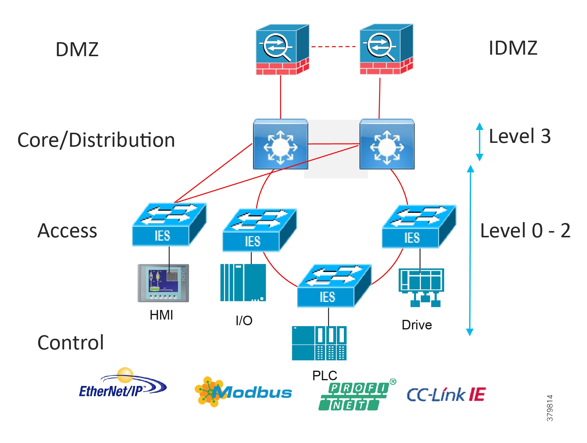
In small-to-medium plants, it is possible to collapse the core into the distribution switches as shown in Figure 9. However, for large plants, in which a large number of Cell/Area Zones exist, this level of hierarchical segmentation is not recommended and a traditional three-tier layer is deployed.
Figure 9 Collapsed Core/Distribution
Access Network
The access layer provides the demarcation between the network infrastructure and the devices that leverage that infrastructure. As such, it provides a security, QoS, and policy trust boundary. When looking at the overall IACS network design, the access switch provides the majority of these access layer services and is a key element in enabling multiple IACS network services.
The Cell/Area Zone can be considered an access layer network that is specialized and optimized for IACS networks.
Summary
■![]() Provides endpoints (PCs, controllers, I/O devices, drives, cameras, and so on) and users with access to the network
Provides endpoints (PCs, controllers, I/O devices, drives, cameras, and so on) and users with access to the network
■![]() Enforces security, segmentation, QoS, and policy trust enforcement
Enforces security, segmentation, QoS, and policy trust enforcement
■![]() Labels packets to enforce segmentation
Labels packets to enforce segmentation
■![]() Comprised of rapid convergent ring topologies or parallel access network topologies
Comprised of rapid convergent ring topologies or parallel access network topologies
■![]() Contains potential multicast-rich local traffic flows
Contains potential multicast-rich local traffic flows
■![]() Provides Network Address Translation (NAT) options
Provides Network Address Translation (NAT) options
Access Network Topologies for the Industrial Plant Environments
Traditional enterprise IT networks are modeled predominantly on redundant star topologies as they tend to have better performance and resiliency, however within the IACS networks there are a number of factors that define the layout of the access network. The physical layout of the plant, cost of cabling, and desired availability are three important factors in plants. For example, ring or linear topologies are more cost effective for long production lines; the cost of cabling these long production lines in a redundant star topology is prohibitive and if availability is required a ring topology map be preferred. Newer technologies, such as PRP and HSR, can provide improved ring resiliency and availability for the IACS plant. HSR can provide lossless redundancy over a ring topology and PRP provides lossless redundancy over two diverse, parallel LANs (LAN-A and LAN-B), which could be two separate rings.
The following are key considerations in determining the topology in an IACS environment:
■![]() Physical Layout—Physical layout of the process facility or the production line influences the networking topology. Installation of cabling can be expensive in industrial environments and is significantly higher than that of the enterprise. Star topologies may be cost prohibitive in long production lines; if real-time communication and availability requirements permit, ring network topology can reduce cost.
Physical Layout—Physical layout of the process facility or the production line influences the networking topology. Installation of cabling can be expensive in industrial environments and is significantly higher than that of the enterprise. Star topologies may be cost prohibitive in long production lines; if real-time communication and availability requirements permit, ring network topology can reduce cost.
■![]() Availability—Availability is a key performance metric that contributes to a plant OEE. The design of the network should enforce maximum uptime. Deploying resilient network topologies allows the network to continue to function after a loss of a link or switch failure. Although some of these events may still lead to downtime of the industrial automation and control systems, a resilient network topology may reduce that chance and should improve the recovery time.
Availability—Availability is a key performance metric that contributes to a plant OEE. The design of the network should enforce maximum uptime. Deploying resilient network topologies allows the network to continue to function after a loss of a link or switch failure. Although some of these events may still lead to downtime of the industrial automation and control systems, a resilient network topology may reduce that chance and should improve the recovery time.
■![]() Real-time communications—The requirement for real-time communications dictates that IACS applications are able to reliably communicate over the network with a level of predictability. Multiple factors, including bandwidth and network hops, can cause latency, jitter, and unpredictable performance. Dedicated star network topologies are better equipped to provide reliable communications, but would have higher cabling costs.
Real-time communications—The requirement for real-time communications dictates that IACS applications are able to reliably communicate over the network with a level of predictability. Multiple factors, including bandwidth and network hops, can cause latency, jitter, and unpredictable performance. Dedicated star network topologies are better equipped to provide reliable communications, but would have higher cabling costs.
Cell/Area Zone Linear Topology
Linear topologies are a chain of switches connected in a serial fashion. This design has the following characteristics:
■![]() Potential bottlenecks (between the distribution and adjacent Layer 2 switch)
Potential bottlenecks (between the distribution and adjacent Layer 2 switch)
■![]() Ease of implementation
Ease of implementation
■![]() Reduced cabling costs
Reduced cabling costs
■![]() Lack of resiliency
Lack of resiliency
■![]() Higher degree of flexibility for a factory floor layout
Higher degree of flexibility for a factory floor layout
Figure 10 Cell/Area Zone Linear Topology
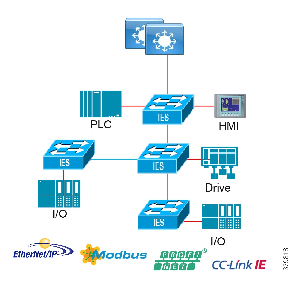
Cell/Area Zone Redundant Star Topology
Figure 11 shows a redundant star architecture. There are only two hops in the path between devices and there is redundancy to provide fast convergence. The network has an element of predictability because of the consistent number of hops in the path. The following are key characteristics of this network topology:
■![]() Predictable path with two hops between any access Layer 2 switch
Predictable path with two hops between any access Layer 2 switch
■![]() Redundant links and resiliency in case of multiple link failures
Redundant links and resiliency in case of multiple link failures
■![]() Faster predictable convergence than rings (other than lossless ring resiliency technologies)
Faster predictable convergence than rings (other than lossless ring resiliency technologies)
■![]() Most expensive cabling design
Most expensive cabling design
Figure 11 Cell/Area Zone Redundant Star Topology
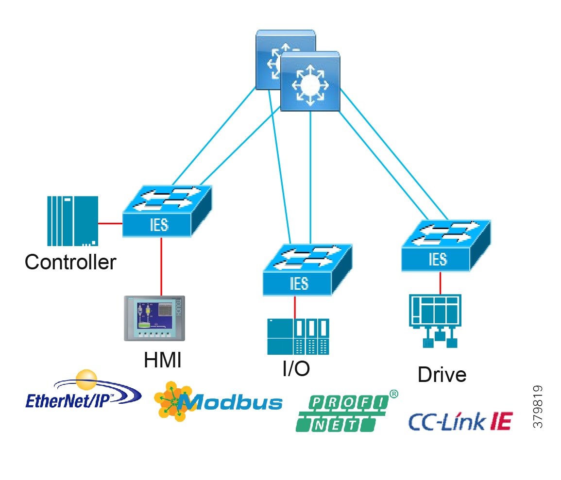
Cell/Area Zone Ring Topologies
The ring topology provides resiliency in that there is always a network path available even with a single link failure. It is a progression of the linear topology, with the last switch in the chain being connected back to the distribution switch to form a ring. The ring shares dual paths around the ring and can reduce bottlenecks and oversubscription. With newer technologies described in the Cell/Area Zone design section, the resiliency can be hitless in a ring deployment. Key considerations of the ring topology include:
■![]() Simplicity, which reduces cabling costs
Simplicity, which reduces cabling costs
■![]() Resiliency from the loss of one network connection
Resiliency from the loss of one network connection
■![]() Hitless or lossless technologies can be deployed with High-Availability Seamless Redundancy (HSR)
Hitless or lossless technologies can be deployed with High-Availability Seamless Redundancy (HSR)
Figure 12 Cell/Area Zone Ring Topology
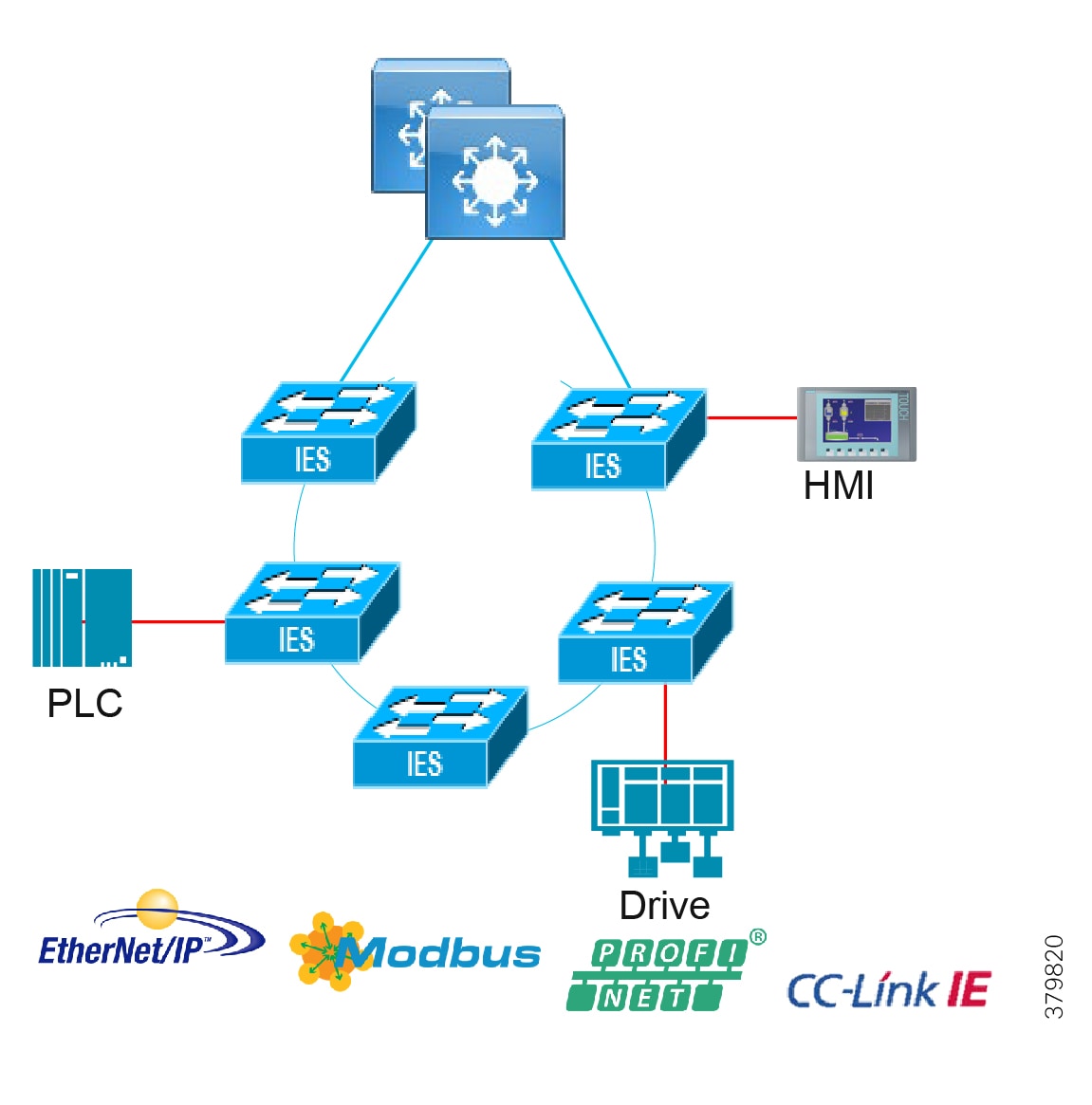
Table 3 summarizes the IACS network topology option advantages and disadvantages for the access network.
| | | |
| | | |
| | | |
| | | |
Converging the enterprise model with the IACS applications and Purdue model, we have the high-level reference architecture in Figure 13. This scheme maps core, distribution, and access layers, site operations and control, and the Cell/Area Zone. This is the wired network reference architecture only.
Figure 13 Industrial Automation Network Model and IACS Reference Architecture
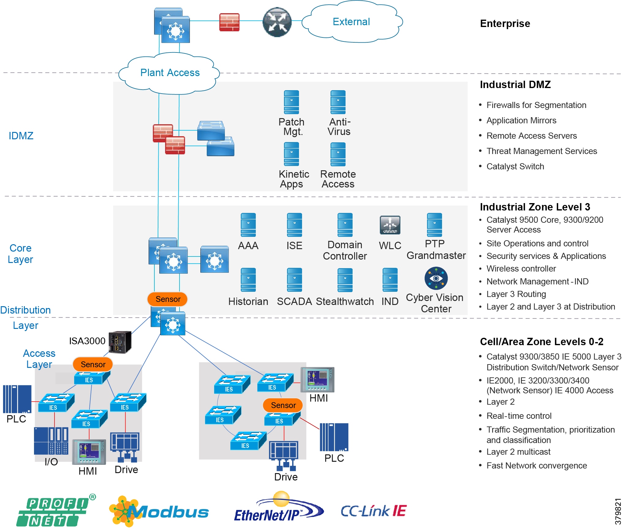
Multiservice Traffic (Non-Operational Applications)
Multiple services can be deployed in plants to support plant operations communications. The services are not part of the operational systems and applications running within the IACS infrastructure. These services typically include physical security badge access, video surveillance, and business enabling applications such as email, telephony, and voice systems. Segmentation of the multi-service applications from the IACS system is a common requirement. Regulatory demands, security concerns, risk management, and confidence of the business to maintain multi-service traffic on the same infrastructure as the IACS process and assets will drive the multi-service architecture.
There are two models that may be considered based on risk acceptance. Generally, a separate physical infrastructure for the non-operational applications and services is acceptable. This in essence is an extended enterprise where the non-operational assets move into non-carpeted space. Figure 14 illustrates a connection from the enterprise into the industrial plant and therefore extends the enterprise network. Hardened industrial switches are used in areas where more traditional enterprise switches cannot be deployed. Assets such as phones or video cameras may also require hardening. The other option could be to deploy services on the same physical infrastructure in Level 3 and extend the services through the industrial DMZ from the enterprise. A separate switch network could be deployed off of the Level 3 core or distribution switches, which could keep the services off of the process networks. Additional consideration must be given to mixed Enterprise/IACS QoS model and bandwidth utilization to help ensure IACS traffic is prioritized and maintains determinism.
Figure 14 Industrial Automation with Extended Enterprise
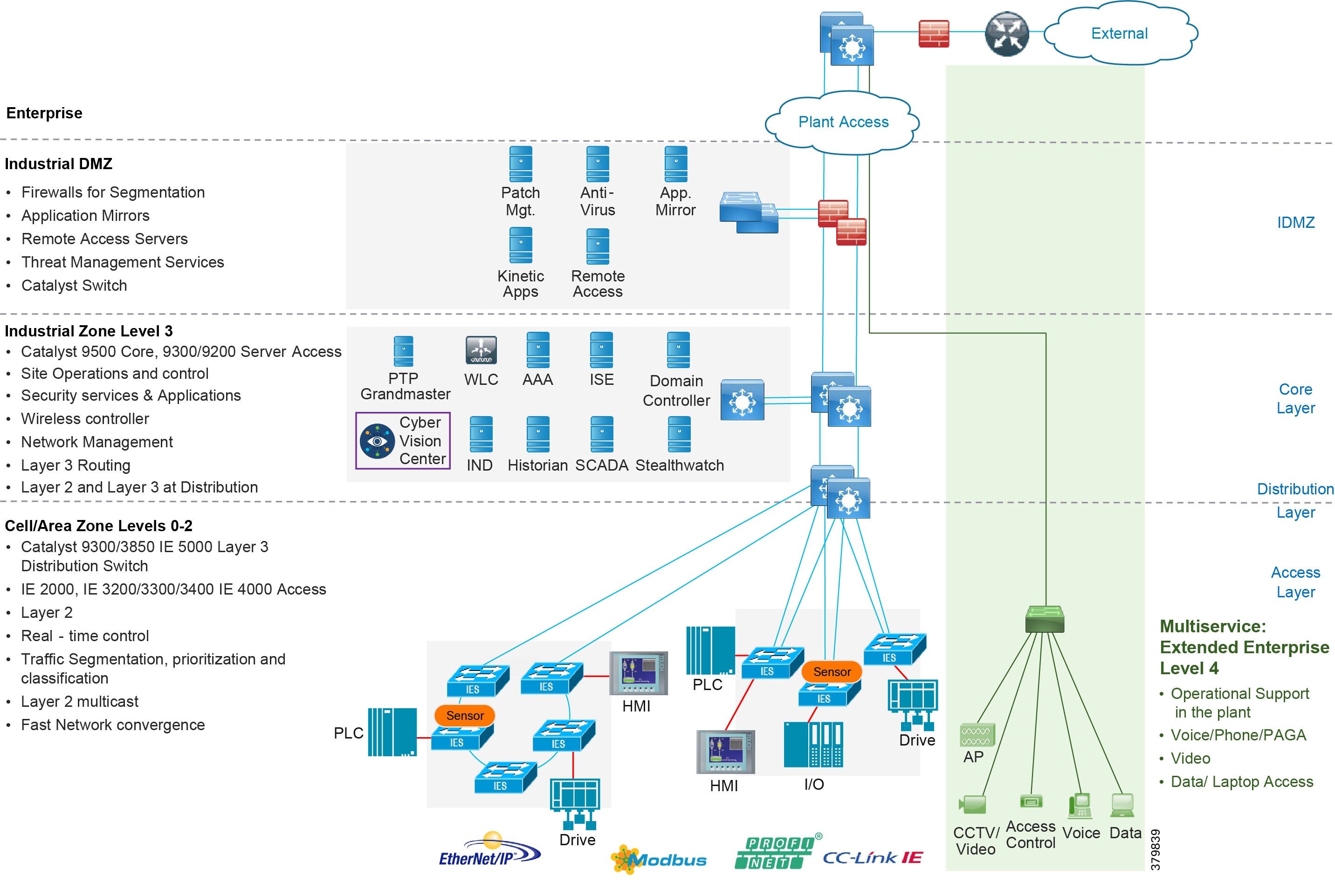
Utility Substation Architecture
Utility substation communication architectures have much in common with other industries. Industrial Automation and utilities both have process networks, DMZ, operations and control, ruggedization, and timing requirements. However this CVD is focused on the implementation and design at the IACS process network layer within the Cell/Area Zone in industrial plants. Electronic Security Perimeter (ESP) in substations is very different. From a functional block perspective, Figure 15 aligns the two architectures of an industrial automation plant and a utility substation.
Figure 15 Utility Substation Architecture
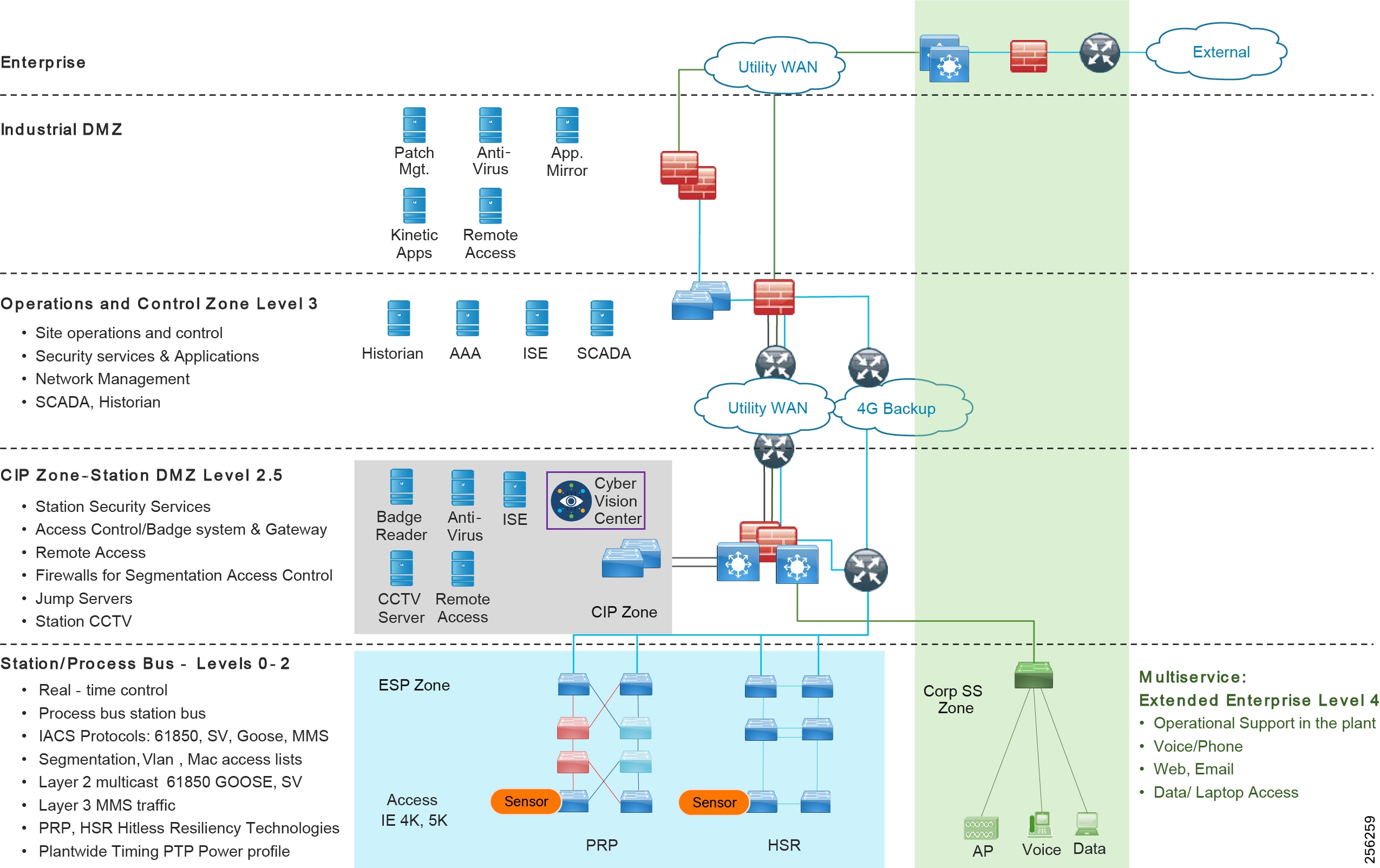
The main difference is that the Level 3 operations within the utilities substation architectures are centralized and off-site, whereas in the manufacturing and processing facility this would normally be on-site where the IACS process is running. The centralized substation operations layer has a control center which monitors multiple substations across geographically separate locations over a wide area network (WAN) in what is known as distributed automation. An industry that has a similar architecture is oil and gas for the transport and distribution of the product along the length of the pipeline. Pipeline stations are distributed along the length of a pipeline and the process is managed centrally at a control center (note that larger pipeline stations and utility substations could have localized control for specific IACS within the facility.)
■![]() Critical Infrastructure Protection—A DMZ is seen on location in both the industrial plant architecture and the utilities architecture. Within the utilities this DMZ is the Critical Infrastructure and Protection Zone. Although slightly different in that the plant has this above the site level operations layer and the utilities substation has this at the station edge below the operations layer, the function remains the same. The DMZ protects the process and automation Industrial Zone in the plant and the CIP protects the ESP in the utilities substation, providing segmentation and separation between the zones as well as controlled access into the ESP. Services within the CIP aligned include Remote Access, Physical security logging, and authentication, authorization, and accounting (AAA).
Critical Infrastructure Protection—A DMZ is seen on location in both the industrial plant architecture and the utilities architecture. Within the utilities this DMZ is the Critical Infrastructure and Protection Zone. Although slightly different in that the plant has this above the site level operations layer and the utilities substation has this at the station edge below the operations layer, the function remains the same. The DMZ protects the process and automation Industrial Zone in the plant and the CIP protects the ESP in the utilities substation, providing segmentation and separation between the zones as well as controlled access into the ESP. Services within the CIP aligned include Remote Access, Physical security logging, and authentication, authorization, and accounting (AAA).
■![]() Corporate SubStation (CorpSS)—Enterprise and operational support services such as voice, web access, and email are located in the CorpSS Zone within the utilities substation. The design for this zone follows a similar ethos to that of the Multiservice Zone in the industrial plant. It is an extension of the enterprise, delivered over a WAN, and segmented from the ESP Process zone. Within an industrial plant these multiservices and enterprise services would also be segmented from the industrial IACS network. Logical versus physical segmentation for the deployment of multiservices is discussed in this CVD for the industrial plant.
Corporate SubStation (CorpSS)—Enterprise and operational support services such as voice, web access, and email are located in the CorpSS Zone within the utilities substation. The design for this zone follows a similar ethos to that of the Multiservice Zone in the industrial plant. It is an extension of the enterprise, delivered over a WAN, and segmented from the ESP Process zone. Within an industrial plant these multiservices and enterprise services would also be segmented from the industrial IACS network. Logical versus physical segmentation for the deployment of multiservices is discussed in this CVD for the industrial plant.
■![]() ESP Zone—The ESP zone is the zone where critical utility monitoring and controlling infrastructure resides. Devices like remote terminal units (RTU), Intelligent Electronic Devices (IED), PLC, relays, and so on all reside within the ESP zone. It is akin to the level 0-2 within the Purdue model. This ESP Zone contains the Station and Process buses. The Station Bus connects the entire substation and provides connectivity between central management and individual bays. The Station Bus connects IEDs within a bay, bays to each other, and bays with the gateway router. The process bus connects the primary measurement and control equipment and I/0 to the IEDs. Typically limited to a bay, however busbar protection and differential protection traffic might span multiple bays.
ESP Zone—The ESP zone is the zone where critical utility monitoring and controlling infrastructure resides. Devices like remote terminal units (RTU), Intelligent Electronic Devices (IED), PLC, relays, and so on all reside within the ESP zone. It is akin to the level 0-2 within the Purdue model. This ESP Zone contains the Station and Process buses. The Station Bus connects the entire substation and provides connectivity between central management and individual bays. The Station Bus connects IEDs within a bay, bays to each other, and bays with the gateway router. The process bus connects the primary measurement and control equipment and I/0 to the IEDs. Typically limited to a bay, however busbar protection and differential protection traffic might span multiple bays.
Figure 16 from IEC 61850 illustrates the architecture for the ESP and the process and station buses.
Figure 16 IEC 61850 Station Bus, Process Bus, and Traffic Example
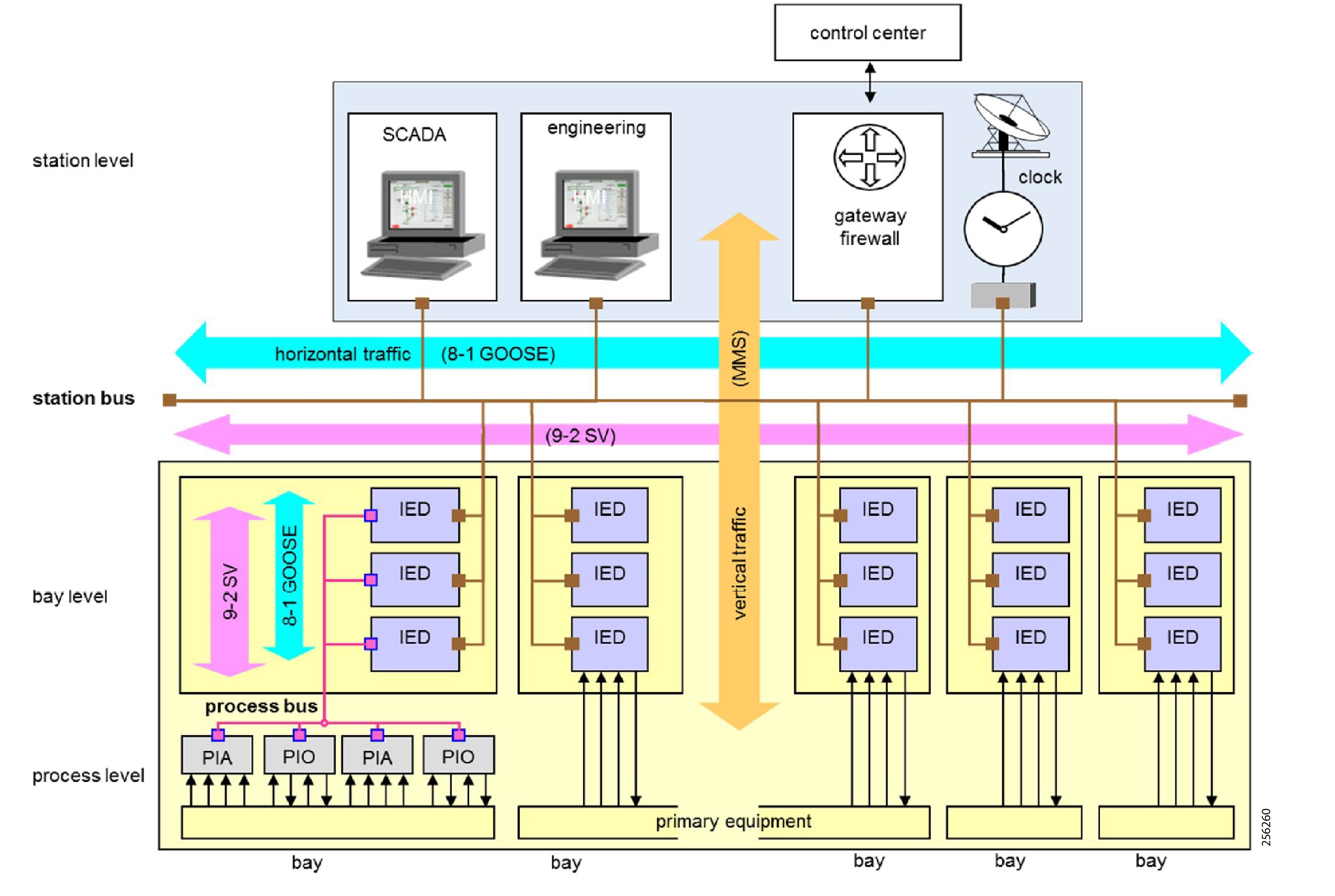
At the process layer on the surface there are similar design considerations. Both architectures require ruggedization, secure segmentation, Layer 2 networking, multicast support, real-time network performance, and high availability to preserve the integrity and performance of the IACS process. However, it is key to understand the traffic types defined within 61850 as this drives the differentiation in design at the process layer between a substation implementation and an industrial plant (the following are the traffic class definitions as taken from IEC-61850-90-4 Ed1). 61850 utilizes GOOSE and Sample value traffic within a substation architecture. GOOSE allows IEDs to exchange data "horizontally" in a bay or between bays. It is used for tasks such as interlocking, measurements, and tripping of circuit breakers. Based on Layer 2 multicast traffic, GOOSE usually flows over the station bus but can extend to the process bus and even the WAN. Sampled Values is mainly used to transmit analogue values (current and voltage) from the sensors to the IEDs. This traffic flows normally on the process bus but can also flow over the station bus. This traffic is also Layer 2 multicast. MMS traffic allows an MMS client such as the SCADA, an OPC server, or a gateway to access "vertically" all IED objects. This is regular Layer 3 IP unicast traffic.
With the dominance of no IP header, EtherType multicast for GOOSE, and SV traffic, the design has to be carefully planned. The process bus generally sets a limit of six devices within a process bus due to the high rate of SV traffic. Filtering of traffic is manually created with very scoped VLAN design and MAC address access lists to restrict bandwidth. This manual definition from planning to implementation is more complex and needs to consider a well-defined VLAN and VLAN trunking design to permit cross station traffic flow of GOOSE and SV because nothing is routed. Not having an IP header in the traffic flow restricts the use of NetFlow to baseline traffic in the ESP with GOOSE and SV traffic, however the MMS traffic and other IP-based traffic would be visible and could still be used to identify anomalies in the substation as documented in this guide. The security architecture would be potentially different as the segmentation scheme is primarily bandwidth derived to restrict or permit multicast traffic across the station with scoped VLANs and Layer 2 multicast access lists. The value of TrustSec and a centralized security implementation (as defined for the industrial plant) for MMS flows needs to be assessed.
Table 4 summarizes the key design consideration for the Cell/Area Zone versus ESP in the areas of performance, availability, multicast, traffic management, and security. These are the areas of design and validation documented in this CVD. Availability and redundancy use similar redundancy protocols. Therefore, with the differences in design the only validation in this CVD specific to substation utility ESP is HSR and PRP in the area of redundancy. With the differences explained previously and referenced in Table 4, the specific substation design guide will provide design guidance for the ESP zone.
| | | |
| | | 61850 GOOSE, SV, MMS |
| | | |
| | | |
| | | |
| | | |
| | | https://www.cisco.com/c/en/us/products/switches/industrial-ethernet-switches/index.html |
| | | |
Industrial Networking and Security Design for the Cell/Area Zone
Design Overview and Deliverables
This section describes the industrial automation networking and security architecture for services, applications, equipment, and devices found in industrial plant environments. The industrial wired network solution design has a large amount of commonalities across various industries and the objective is to promote re-use where possible. The design could be referenced for a large-scale auto manufacturer, a pharmaceutical producer, a mine, oil and gas processing facility, or refinery.
At a high level, key deliverables in this guide include providing Cell/Area Zone network and security design and laying the foundation for multiple IACS applications that will reside on this framework. The validation focuses on the Cell/Area Zone networks in these plants with new resiliency protocol support, advanced security providing visibility, segmentation, and anomaly detection, and the introduction of the Cisco next generation Industrial Ethernet switches, the Cisco IE 3200, Cisco IE 3300, and Cisco IE 3400 in additional to other Cisco Industrial Ethernet switching products such as Cisco IE 2000, Cisco IE 4000, and Cisco IE 5000. Key functions and new platforms included in this phase of the Industrial Automation CVD include:
■![]() SDA-Ready Platforms —Introduction and validation of the Cisco Catalyst 9300 switch as the distribution switch for the Cell/Area Zone. The Cisco Catalyst 9300 platform is the next generation platform that supports SDA today. SDA is the industry's first intent-based networking solution for the enterprise built on the principles of the Cisco Digital Network Architecture (DNA). SDA provides automated configuration and end-to-end segmentation to separate user, device, and application traffic without redesigning the network. SDA automates user access policy so organizations can make sure the right policies are established for any user or device with any application across the network. Ease of management and intent-driven networking with policy will be valuable additions for the industrial plant environments. Cisco is leveraging SDA in our Cisco IoT Extended Enterprise solutions for non-carpeted spaces (see www.cisco.com/go/iotcvd) where IT manages portions of industrial plants, warehouses, parking lots, roadways/intersections, etc. However, SDA is not yet validated for deployment to support industrial automation and control (the control loop) applications in the Cell/Area Zone in this solution. The new IE platforms are being positioned in the architecture to prepare for when SDA is able to support Cell/Area Zone industrial automation and control application requirements and protocols. The architecture is promoting SDA switch ready.
SDA-Ready Platforms —Introduction and validation of the Cisco Catalyst 9300 switch as the distribution switch for the Cell/Area Zone. The Cisco Catalyst 9300 platform is the next generation platform that supports SDA today. SDA is the industry's first intent-based networking solution for the enterprise built on the principles of the Cisco Digital Network Architecture (DNA). SDA provides automated configuration and end-to-end segmentation to separate user, device, and application traffic without redesigning the network. SDA automates user access policy so organizations can make sure the right policies are established for any user or device with any application across the network. Ease of management and intent-driven networking with policy will be valuable additions for the industrial plant environments. Cisco is leveraging SDA in our Cisco IoT Extended Enterprise solutions for non-carpeted spaces (see www.cisco.com/go/iotcvd) where IT manages portions of industrial plants, warehouses, parking lots, roadways/intersections, etc. However, SDA is not yet validated for deployment to support industrial automation and control (the control loop) applications in the Cell/Area Zone in this solution. The new IE platforms are being positioned in the architecture to prepare for when SDA is able to support Cell/Area Zone industrial automation and control application requirements and protocols. The architecture is promoting SDA switch ready.
■![]() Next Generation Industrial Ethernet Switching —The Cisco IE 3200, Cisco IE 3300, and Cisco IE 3400 are Cisco next generation Industrial Ethernet switches. These switches are inserted into the Cell/Area Zone for Industrial Automation. As part of the SDA readiness the Cisco IE 3400 switch will be the industrial Ethernet switching platform that will support the SDA Fabric edge switch functionality. The Cisco IE 3400 and Cisco Catalyst 9300 switches will provide a foundation to move towards SDA in the wired infrastructure. This will provide a platform to enable SDA features as they become available. Today these platforms will be deployed as non-SDA enabled switches, performing traditional network switching functions.
Next Generation Industrial Ethernet Switching —The Cisco IE 3200, Cisco IE 3300, and Cisco IE 3400 are Cisco next generation Industrial Ethernet switches. These switches are inserted into the Cell/Area Zone for Industrial Automation. As part of the SDA readiness the Cisco IE 3400 switch will be the industrial Ethernet switching platform that will support the SDA Fabric edge switch functionality. The Cisco IE 3400 and Cisco Catalyst 9300 switches will provide a foundation to move towards SDA in the wired infrastructure. This will provide a platform to enable SDA features as they become available. Today these platforms will be deployed as non-SDA enabled switches, performing traditional network switching functions.
■![]() Lossless Resiliency Protocols —New lossless resiliency protocols and technologies that can be considered for deployment across industries with the introduction of Parallel Redundancy Protocol (PRP), High-Availability Seamless Redundancy (HSR), and the HSR/PRP combined box. Industrial automation applications can have very strict availability requirements that must be adhered to and the network resiliency design and network topologies are critical in helping adhere to these requirements. Cisco Industrial Ethernet platforms Cisco IE 4000, Cisco IE 4010, and Cisco IE 5000 support lossless redundancy protocols HSR and PRP. These aid in keeping the network highly available in supporting the industrial applications within the Cell/Area Zone.
Lossless Resiliency Protocols —New lossless resiliency protocols and technologies that can be considered for deployment across industries with the introduction of Parallel Redundancy Protocol (PRP), High-Availability Seamless Redundancy (HSR), and the HSR/PRP combined box. Industrial automation applications can have very strict availability requirements that must be adhered to and the network resiliency design and network topologies are critical in helping adhere to these requirements. Cisco Industrial Ethernet platforms Cisco IE 4000, Cisco IE 4010, and Cisco IE 5000 support lossless redundancy protocols HSR and PRP. These aid in keeping the network highly available in supporting the industrial applications within the Cell/Area Zone.
■![]() Network Visibility and OT Management —Visibility and identification of IACS devices, assets, and communication in Cell/Area Zone(s) with Cisco Cyber Vision and the Cisco Industrial Network Director (IND). Cisco Cyber Vision gives OT teams and network managers full visibility of their assets and application flows so they can implement security best practices, drive network segmentation projects, and reduce security risks. Cisco Cyber Vision automatically uncovers the smallest details of the production infrastructure: vendor references, firmware and hardware versions, serial numbers, PLC rack slot configuration, and so on. It identifies asset relationships, communication patterns, changes to variables, and more. This detailed information is shown in various maps, tables, and reports that maintain a complete inventory of industrial assets, their relationships, their vulnerabilities, and the programs they run, providing operations-centric network management for industrial Ethernet networks. The system supports industrial automation protocols such as ODVA, Inc. Common Industrial Protocol (CIP), PROFINET, OPC-UA, Modbus, BACnet, and so on to discover automation devices such as PLC, IO, HMI, and drives and delivers an integrated topology map of automation and networking assets to provide a common framework for plant OT and IT personnel to manage and maintain the industrial network. This information can be presented to Cisco Stealthwatch to provide context to assets and help with attribution for security monitoring.
Network Visibility and OT Management —Visibility and identification of IACS devices, assets, and communication in Cell/Area Zone(s) with Cisco Cyber Vision and the Cisco Industrial Network Director (IND). Cisco Cyber Vision gives OT teams and network managers full visibility of their assets and application flows so they can implement security best practices, drive network segmentation projects, and reduce security risks. Cisco Cyber Vision automatically uncovers the smallest details of the production infrastructure: vendor references, firmware and hardware versions, serial numbers, PLC rack slot configuration, and so on. It identifies asset relationships, communication patterns, changes to variables, and more. This detailed information is shown in various maps, tables, and reports that maintain a complete inventory of industrial assets, their relationships, their vulnerabilities, and the programs they run, providing operations-centric network management for industrial Ethernet networks. The system supports industrial automation protocols such as ODVA, Inc. Common Industrial Protocol (CIP), PROFINET, OPC-UA, Modbus, BACnet, and so on to discover automation devices such as PLC, IO, HMI, and drives and delivers an integrated topology map of automation and networking assets to provide a common framework for plant OT and IT personnel to manage and maintain the industrial network. This information can be presented to Cisco Stealthwatch to provide context to assets and help with attribution for security monitoring.
■![]() Cisco Cyber Vision —Gives OT engineers real-time insight on the actual industrial process status, such as unexpected variable changes or controller modifications. They can take action to maintain system integrity and production continuity. Cyber experts can easily dive into all this data to analyze attacks and find the source. CISOs have all the information to document their incident reports. Cisco Cyber Vision "understands" the proprietary OT protocols used by automation equipment, so it can track process anomalies, errors, misconfigurations, and unauthorized industrial events. It also records everything and so serves as a kind of "flight recorder" of the industrial infrastructure.
Cisco Cyber Vision —Gives OT engineers real-time insight on the actual industrial process status, such as unexpected variable changes or controller modifications. They can take action to maintain system integrity and production continuity. Cyber experts can easily dive into all this data to analyze attacks and find the source. CISOs have all the information to document their incident reports. Cisco Cyber Vision "understands" the proprietary OT protocols used by automation equipment, so it can track process anomalies, errors, misconfigurations, and unauthorized industrial events. It also records everything and so serves as a kind of "flight recorder" of the industrial infrastructure.
Cisco Cyber Vision combines protocol analysis, intrusion detection, and behavioral analysis to detect any attack tactic. This holistic approach ensures Cisco Cyber Vision can detect both known and unknown attacks as well as malicious behaviors that could be warning signs of an attack. Cisco Cyber Vision integrates seamlessly with IT SOC (Security Operation Centers) so security analysts can trace industrial events in their SIEM for OT and IT correlation and automatically trigger firewall filter rules in the event of an attack.
■![]() TrustSec and Enhanced Segmentation —A key component for security implementations and detailed in IEC 62443-3-3 is segmentation of assets into group-based policies. What assets and users need to communicate within a Cell/Area Zone and external to the Cell/Area Zone across an industrial plant needs to be defined. Cisco Cyber Vision provides the visibility of the connected assets to Cisco ISE. Cisco ISE creates and administers the policy defined by the security and OT teams across a Cisco infrastructure. This guide includes recommendations and validation for assets discovery, policy definition, and TrustSec application across a Cisco-managed infrastructure for an industrial plant which can be deployed across industries.
TrustSec and Enhanced Segmentation —A key component for security implementations and detailed in IEC 62443-3-3 is segmentation of assets into group-based policies. What assets and users need to communicate within a Cell/Area Zone and external to the Cell/Area Zone across an industrial plant needs to be defined. Cisco Cyber Vision provides the visibility of the connected assets to Cisco ISE. Cisco ISE creates and administers the policy defined by the security and OT teams across a Cisco infrastructure. This guide includes recommendations and validation for assets discovery, policy definition, and TrustSec application across a Cisco-managed infrastructure for an industrial plant which can be deployed across industries.
■![]() Security using NetFlow and Stealthwatch for Anomaly Detection —This guide includes design recommendations for implementing Stealthwatch and enabling NetFlow to provide anomaly detection within the Industrial zone of a plant for multiple industries. Further visibility into the traffic traversing the plant infrastructure can aid with troubleshooting and highlight abnormal behaviors such as detection of malware that is sprawling across a plant. With the Cisco IE 3400, Cisco IE 4000, Cisco IE 4010, and Cisco IE 5000 switches, NetFlow can be enabled to provide data flow metrics to Stealthwatch. Stealthwatch takes the flow data from the network and has many inbuilt machine learning algorithms that can assist an IT security professional in detecting possible malware propagation in the network.
Security using NetFlow and Stealthwatch for Anomaly Detection —This guide includes design recommendations for implementing Stealthwatch and enabling NetFlow to provide anomaly detection within the Industrial zone of a plant for multiple industries. Further visibility into the traffic traversing the plant infrastructure can aid with troubleshooting and highlight abnormal behaviors such as detection of malware that is sprawling across a plant. With the Cisco IE 3400, Cisco IE 4000, Cisco IE 4010, and Cisco IE 5000 switches, NetFlow can be enabled to provide data flow metrics to Stealthwatch. Stealthwatch takes the flow data from the network and has many inbuilt machine learning algorithms that can assist an IT security professional in detecting possible malware propagation in the network.
Cell/Area Zone Design and Recommendations
Figure 17 Industrial Automation Network Model and IACS Reference Architecture
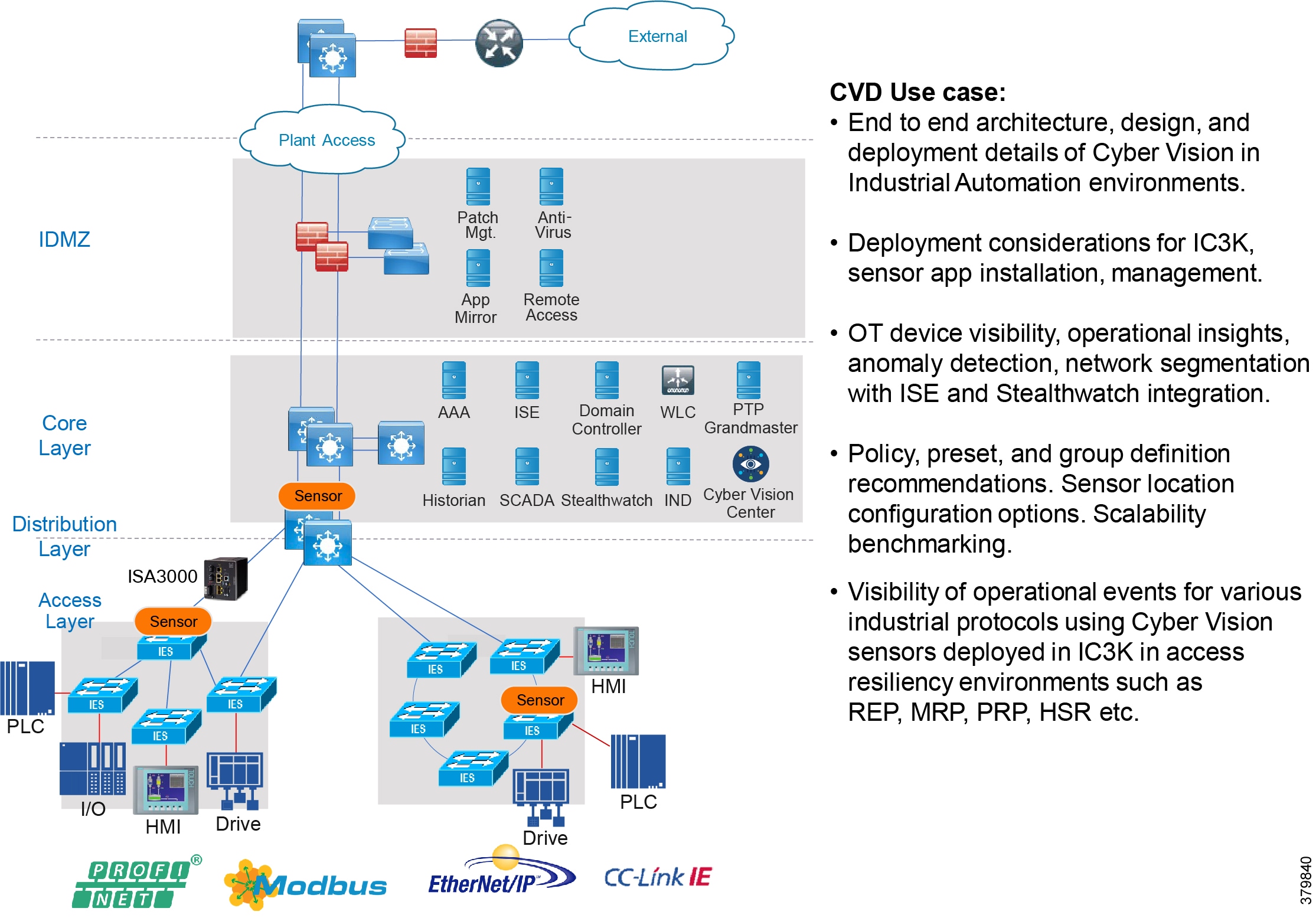
The Industrial zone contains the Site Operations (Level 3) and the Cell/Area Zone (Levels 0-2). The Cell/Area Zone comprises all of the systems, devices, controllers, and applications to keep the plant floor production or processes running. It is extremely important to preserve smooth plant floor operations and functions, therefore security, segmentation, and availability best practices are key components of the design.
The Cell/Area Zone is the key functional zone where IACS devices and controllers are executing the real-time control of an industrial process. This network connects sensors, actuators, drives, controllers, and any other IACS devices that need to communicate in real-time I/O communication. It is essentially the major building block within the Industrial Automation architecture.
Figure 18 Cell/Area Zone
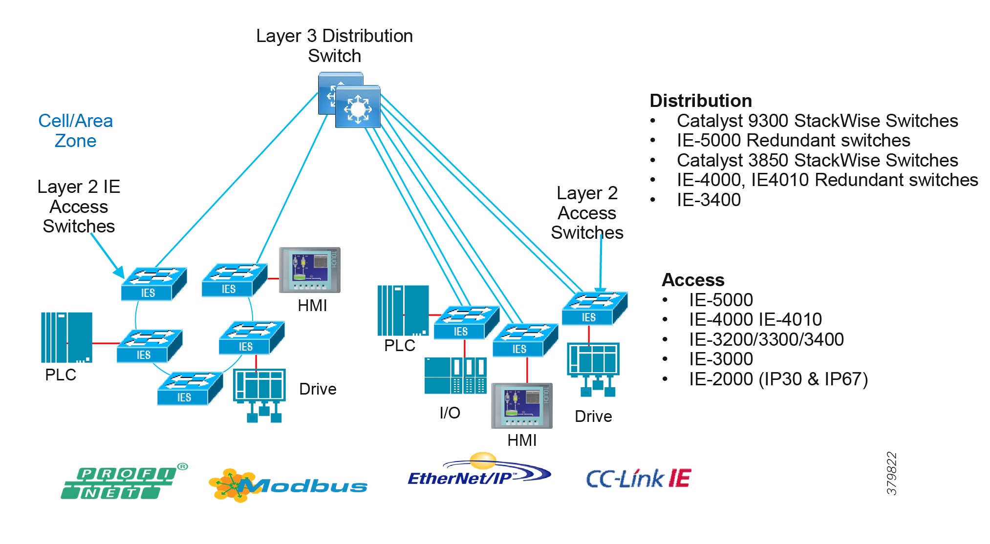
Industrial Characteristics and Design Considerations
The Cell/Area Zone is an access network, but has very different requirements than a traditional IT access layer network. There are key requirements and industrial characteristics that the networking platforms must align with and support. Environmental conditions such as temperature, humidity, and invasive materials require different physical attributes from a networking platform. In addition, continuous availability is critical to ensure the uptime of the industrial process to minimize impact to revenue. Finally, industrial networks also differ from IT in that they need IACS protocol support to integrate with IACS systems.
The following highlights the key design considerations for the Cell/Area Zone, which will directly impact the platform selection, network topology, security implementation, and overall design:
■![]() Industrial Characteristics—Environmental conditions, plant layout, and cabling costs all impact the platform choices and network topology in the design. Industrial plants and processing facilities generally require physically hardened platforms in the Cell/Area Zone. Mines, oil and gas refineries, and plant environments are subject to harsh physical conditions that an IT networking platform cannot withstand. Hardened platforms are equipped for extended temperature ranges, shock and vibration, and invasive materials.
Industrial Characteristics—Environmental conditions, plant layout, and cabling costs all impact the platform choices and network topology in the design. Industrial plants and processing facilities generally require physically hardened platforms in the Cell/Area Zone. Mines, oil and gas refineries, and plant environments are subject to harsh physical conditions that an IT networking platform cannot withstand. Hardened platforms are equipped for extended temperature ranges, shock and vibration, and invasive materials.
■![]() Interoperability and Interconnectivity—Within the Industrial Zone, Ethernet provides the best technology to interconnect IACS devices and protocols. IACS vendors are adopting the OSI model with Ethernet as the standard to provide communication for a mixture of IACS devices, controllers, and management servers over the network. However, the network must be engineered to support the IACS implementations with an emphasis on real-time communications, availability, and segmentation.
Interoperability and Interconnectivity—Within the Industrial Zone, Ethernet provides the best technology to interconnect IACS devices and protocols. IACS vendors are adopting the OSI model with Ethernet as the standard to provide communication for a mixture of IACS devices, controllers, and management servers over the network. However, the network must be engineered to support the IACS implementations with an emphasis on real-time communications, availability, and segmentation.
■![]() Real-Time Communications, Determinism, and Performance—Packet delay and jitter within an IACS network can have significant impact to the underlying industrial process. Depending on the industrial application, a delay or variance and lack of determinism in the network can shut down an industrial process and impact its overall efficiency. Achieving predictable, reliable packet delivery is a fundamental requirement for a successful network design in the Cell/Area Zone. A design will need to factor the number of network hops, bandwidth requirements, and network QoS and prioritization to provide a greater degree of determinism and performance for the real-time applications and functions. Precision Time Protocol (PTP) can also help with the deterministic nature of the network and applications.
Real-Time Communications, Determinism, and Performance—Packet delay and jitter within an IACS network can have significant impact to the underlying industrial process. Depending on the industrial application, a delay or variance and lack of determinism in the network can shut down an industrial process and impact its overall efficiency. Achieving predictable, reliable packet delivery is a fundamental requirement for a successful network design in the Cell/Area Zone. A design will need to factor the number of network hops, bandwidth requirements, and network QoS and prioritization to provide a greater degree of determinism and performance for the real-time applications and functions. Precision Time Protocol (PTP) can also help with the deterministic nature of the network and applications.
■![]() Availability—A key metric within industrial automation is overall equipment effectiveness (OEE). Availability of the critical IACS communications is a key factor that contributes to the OEE score. Network topologies and resiliency design choices, such as QoS and segmentation, are critical in helping maintain availability of IACS applications, reducing the impact of a failure or security breach.
Availability—A key metric within industrial automation is overall equipment effectiveness (OEE). Availability of the critical IACS communications is a key factor that contributes to the OEE score. Network topologies and resiliency design choices, such as QoS and segmentation, are critical in helping maintain availability of IACS applications, reducing the impact of a failure or security breach.
■![]() Security—When discussing industrial network security, customers are concerned with how to keep the environment safe and operational. It is recommended to follow an architectural approach to securing the control system and process domain. The Purdue Model of Control Hierarchy, International Society of Automation 95 (ISA95) and IEC 62443, NIST 800-82, and NERC CIP for utility substations are examples of such architectures. Key security requirements in the Cell/Area Zone include device and IACS asset visibility, secure access to the network, segmentation, group-based security policy, and Layer 2 hardening (control plane and data plane) to protect the infrastructure.
Security—When discussing industrial network security, customers are concerned with how to keep the environment safe and operational. It is recommended to follow an architectural approach to securing the control system and process domain. The Purdue Model of Control Hierarchy, International Society of Automation 95 (ISA95) and IEC 62443, NIST 800-82, and NERC CIP for utility substations are examples of such architectures. Key security requirements in the Cell/Area Zone include device and IACS asset visibility, secure access to the network, segmentation, group-based security policy, and Layer 2 hardening (control plane and data plane) to protect the infrastructure.
■![]() Management—Plant infrastructures are becoming more advanced and connected than ever before. Within the Cell/Area Zone there are two personas and skillsets taking on responsibility of the network infrastructure, namely IT and OT staff. OT teams require an easy-to-use, lightweight, and intelligent platform that presents network information in the context of automation equipment. Key functions at this layer will include plug-and-play, easy switch replacement, and ease of use to maintain the network infrastructure.
Management—Plant infrastructures are becoming more advanced and connected than ever before. Within the Cell/Area Zone there are two personas and skillsets taking on responsibility of the network infrastructure, namely IT and OT staff. OT teams require an easy-to-use, lightweight, and intelligent platform that presents network information in the context of automation equipment. Key functions at this layer will include plug-and-play, easy switch replacement, and ease of use to maintain the network infrastructure.
■![]() Traffic types—The IACS traffic within the Cell/Area Zone is predominantly local and stays within the same Layer 2 domain. Cyclical I/O data communicated on very short intervals (milliseconds) from devices to controllers and workstations or HMIs occurs all on the same LAN or VLAN. Layer 2 multicast is also used in IACS networks.
Traffic types—The IACS traffic within the Cell/Area Zone is predominantly local and stays within the same Layer 2 domain. Cyclical I/O data communicated on very short intervals (milliseconds) from devices to controllers and workstations or HMIs occurs all on the same LAN or VLAN. Layer 2 multicast is also used in IACS networks.
Cell/Area Zone Components
Cisco has an extensive range of Industrial Ethernet switches. Within the Cell/Area Zone at the access layer, environmental conditions as described earlier are usually a key factor in selecting a hardened, DIN-mountable access switch, such as a Cisco IE 3400 or Cisco IE 4000. The Layer 3 distribution switch may have less stringent requirements, allowing for models such as the Cisco Catalyst 3800 and Cisco Catalyst 9300. The distribution switch is typically located in a controlled, carpeted space, however if industrial protocols are still required, the Cisco IE 5000 or Cisco IE 4010 could be deployed at this layer.
Figure 19 Cell/Area Zone Components
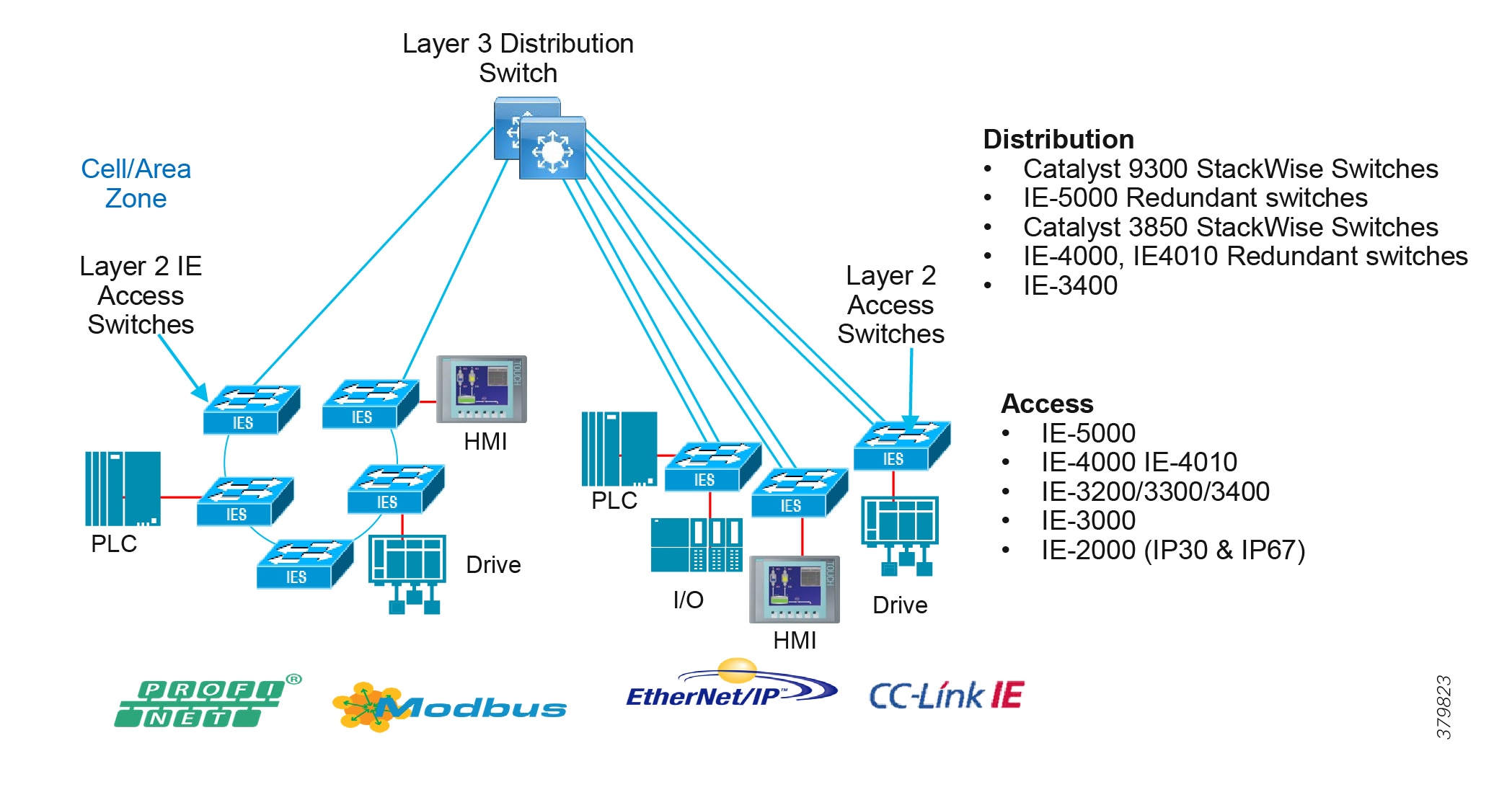
■![]() Levels 0, 1, and 2 components; for example, devices, controllers, and HMIs
Levels 0, 1, and 2 components; for example, devices, controllers, and HMIs
■![]() Layer 2 access switches
Layer 2 access switches
■![]() Layer 3 distribution switches
Layer 3 distribution switches
Table 5 provides guidance on choosing switches based on multiple factors which are critical in industrial environments.
| Features | Cisco Industrial Ethernet (IE) | Typical Non-Industrial Switch |
|---|---|---|
| Form Factor/Mounting Options | Din Rail, Panel, and Rack Mount | Rack Mount |
| Interface Options | Port density 6-28 ports | High port density |
| PoE Density/Max Power | Port density 6-28 ports | High port density |
| Power Supply Options | DC input voltage range = 10 to 300* | DC input voltage range = 36 to 72 |
| Environment Design ■ ■ ■ ■ | ■ ■ ■ ■ | ■ ■ ■ ■ |
| "Swap Drive"—Removable Flash | Yes | No |
| Dying Gasp—Upon loss of input power | Yes | No |
| Alarm Ports | Yes (Inputs on most models and Output on all models) | No |
| Deterministic Ethernet IEEE 802.1 TSN | Yes—Supported on Cisco IE 4000 and Cisco IE 5000 (under development) | No |
| Precise Timing IEEE 1588 PTP IEEE C37.238-2011 (Power Profile) | Yes IEEE 1588, inc. Power Profile level of accuracy (50ns per hop) Option for GPS and IRIG-B on Cisco IE 5000, including Grandmaster with Stratum 3E on-board oscillator | No |
Switching Platform, Industrial Security Appliance, and Industrial Compute Portfolio for the Cell/Area Zone
There has been an evolution of switching platforms since the previous industrial automation architectures and validated designs such as Ethernet to the Factory, CPWE, and Connected Refinery/Processing plant were released. Newer features and hardware capabilities have been added to increase performance, security, and capabilities of the Industrial Automation architecture. The following highlights some of these capabilities that are extremely relevant in this phase of the architecture and also features which show future benefit:
■![]() NetFlow export enabled on industrial switches provides network visibility into the traffic within the Cell/Area Zone. Consuming NetFlow in Cisco Steathwatch provides anomaly detection to help secure the network. NetFlow is available on the Cisco 3400, Cisco IE 4000, Cisco IE 4010, and Cisco IE 5000 switches.
NetFlow export enabled on industrial switches provides network visibility into the traffic within the Cell/Area Zone. Consuming NetFlow in Cisco Steathwatch provides anomaly detection to help secure the network. NetFlow is available on the Cisco 3400, Cisco IE 4000, Cisco IE 4010, and Cisco IE 5000 switches.
■![]() Cisco TrustSec-enabled industrial switches provide scalable segmentation across the industrial automation architecture.
Cisco TrustSec-enabled industrial switches provide scalable segmentation across the industrial automation architecture.
■![]() Network resiliency protocols, such as PRP and HSR, improve availability by providing losslesss failover. Cisco IE 4000, Cisco IE 4010, and Cisco IE 5000 support PRP and HSR deployments.
Network resiliency protocols, such as PRP and HSR, improve availability by providing losslesss failover. Cisco IE 4000, Cisco IE 4010, and Cisco IE 5000 support PRP and HSR deployments.
■![]() Inserting the Cisco IE 3400 (SDA-capable) and Cisco Catalyst 9300 switches into the architecture provides SDA platform readiness and a potential path to intent-based services.
Inserting the Cisco IE 3400 (SDA-capable) and Cisco Catalyst 9300 switches into the architecture provides SDA platform readiness and a potential path to intent-based services.
■![]() The Cyber Vision network sensor on the Cisco IE 3400 and Cisco Catalyst 9300 switches for security monitoring.
The Cyber Vision network sensor on the Cisco IE 3400 and Cisco Catalyst 9300 switches for security monitoring.
Figure 20 shows an extensive industrial switching portfolio for industrial automation plant environments, as well as security and Cisco Cyber Vision. Multiple platforms are available to accommodate various feature requirements. Cisco IND is the management platform to support the industrial switches in the industrial plant environments.
Figure 20 Cisco IoT Industrial Switching, Security, and Cyber Vision Portfolio
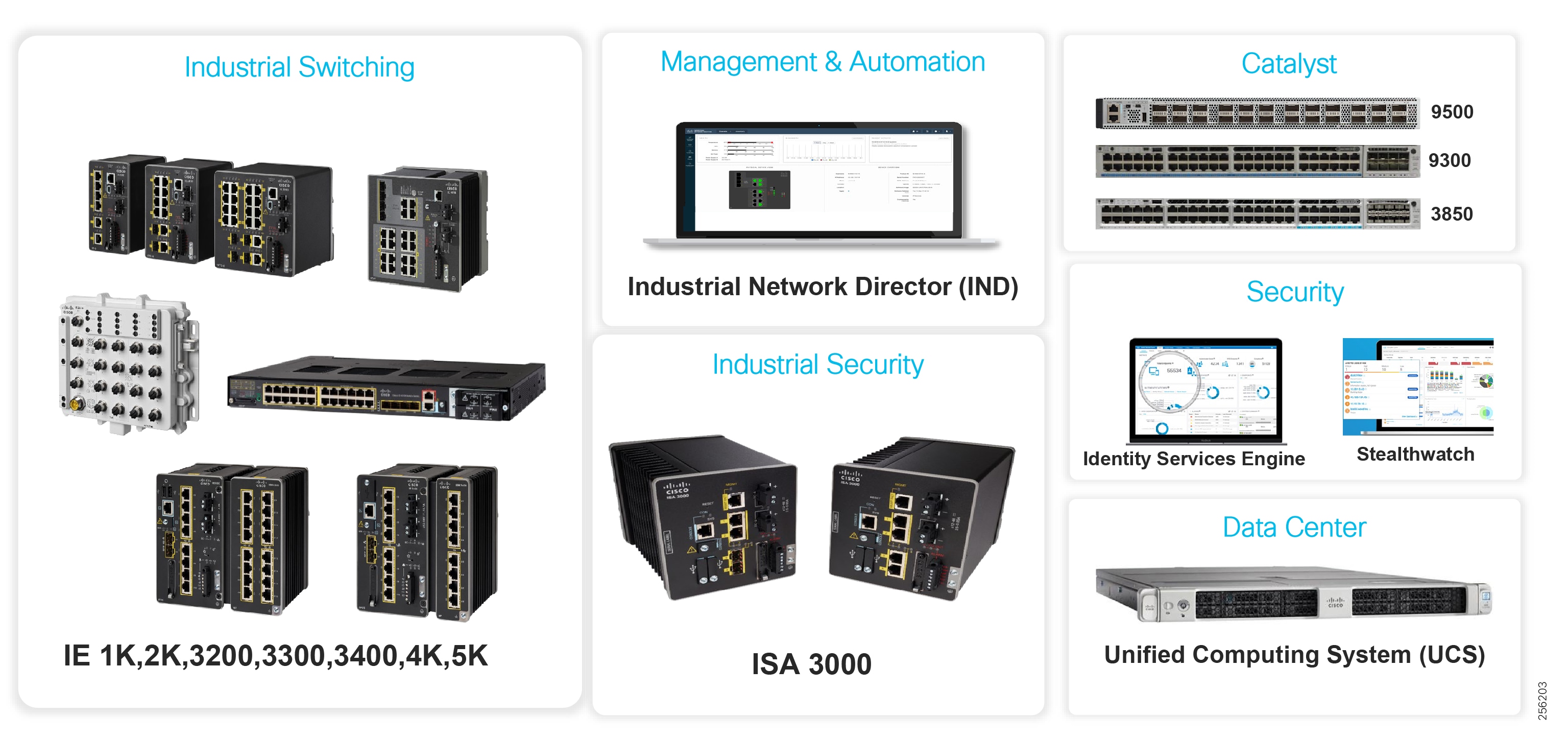
| Cisco IE 2000 access | Cisco IE 4000 access/distribution | Cisco IE 4010 access/distribution | Cisco IE 5000 access/distribution | Cisco IE 3200 access | Cisco IE 3300 access/distribution | Cisco IE 3400 access/distribution | Cisco Catalyst 9300 | |
|---|---|---|---|---|---|---|---|---|
| 19 inch | No | No | Yes | Yes | No | No | No | Yes |
| Din-Rail | Yes | Yes | No | No | Yes | Yes | Yes | No |
| TrustSec | No | Yes | Yes | Yes | N/A | N/A | Yes | Yes |
| dot1X | Yes | Yes | Yes | Yes | Yes | Yes | Yes | Yes |
| QoS | Yes | Yes | Yes | Yes | Yes | Yes | Yes | Yes |
| NetFlow | No | Yes | Yes | Yes | No | HW Ready | Yes | Yes |
| REP | Yes | Yes | Yes | Yes | Yes | Yes | Yes | Yes |
| HSR (HSR-SAN, HSR-PRP) | No | Yes | Yes | Yes | No | No | HW Ready | No |
| PRP (Red box) | No | Yes | Yes | Yes | No | No | HW Ready | No |
| PROFINET | Yes | Yes | Yes | Yes | | | Yes | No |
| MRP | Yes | Yes | Yes | Yes | | | Yes | No |
| IND support | Yes | Yes | Yes | Yes | Yes | Yes | Yes | Yes |
| SDA Extended Node | No | Yes | No | Yes | No | HW Ready | Yes | Yes |
| SDA fabric edge node | No | No | No | No | No | No | Yes | Yes |
| Cisco DNA support | Yes | Yes | Yes | Yes | Yes | Yes | Yes | Yes |
Note: Table 6 shows the software features and capabilities supported at the time of this CVD release. Refer to the product data sheet for the latest feature support:
https://www.cisco.com/c/en/us/products/switches/industrial-ethernet-switches/index.html
Table 7 provides a view of the hardware and software components validated in this version of Industrial Automation CVD.
| Product Role | Product | SW Version |
|---|---|---|
| Access Switch | Cisco IE 4000 | 15.2.7E1 |
| Access Switch | Cisco IE 4010 | 15.2.6E2a |
| Access Switch | Cisco IE 3400 | 17.2.1 |
| Access Switch | Cisco IE 3200 | 17.2.1 |
| Access Switch | Cisco IE 2000 | 15.2.6E2a |
| Access Switch | Cisco IE 1000 | 1.6 |
| Distribution Switch | Cisco IE 5000 | 15.2.7E0s |
| Distribution Switch | Cisco Catalyst 3850 | Denali-16.3.7 |
| Distribution Switch | Cisco Catalyst 9300 | Amsterdam-17.3.1 |
| Core Switch | Cisco Catalyst 6880 | 15.2.1SY1a |
| Firewall Cisco Industrial Firewall | Cisco ASA-5525-X Cisco ISA3000 | 9.4.3, ASDM 7.4.3 6/6. ASDM 7.4.3 |
| Network Discovery | Cisco IND | 1.7 |
| Policy Management | Cisco ISE | 2.7 |
| Anomaly Detection | Cisco Stealthwatch | 7.1.2 |
| Network Visibility | Cisco Cyber Vision Sensor | 3.1.0 |
| Network Visibility | Cisco Cyber Vision Center | 3.1.0 |
| Application Deployment, Management, and Monitoring | Cisco FND | 4.5.1 |
Cell/Area Zone IP Addressing
The IACS devices have to be assigned with IP addresses to communicate with other IACS devices and also with Level 3 site operations. The IP address to the IACS device can be assigned statically or by using DHCP service. This section describes the factors that need to be considered when choosing between static assignment or by DHCP service.
Static IP Addressing
Generally, IACS devices are not moved around the Cell/Area Zone when wired to a port. There is a requirement for ease of use and ease of replacement. The default method used most often is for the operations team to statically assign an IP address to the IACS device. Manual DIP switches or dials for addressing IACS devices are still deployed on plant floors which require static configuration by an operator. For an IACS device in the Cell/Area Zone, the time it takes for a device to come back after the boot process is of vital importance. As a result, if an IACS device is using DHCP, then the time it takes to assign IP address increases the amount of time needed for the device to come up and this behavior impacts the performance of the IACS device. However, as the size of the IP address increases, it becomes difficult to manage the IP address table.
Assigning IP Addresses Using DHCP
Assigning IP addresses to IACS devices using DHCP is an alternative method to static assignment. This method resolves the problems pertaining to static assignment, management of IP addresses and changing IP address of the IACS devices because DCHP protocol is an automatic process that allows for an IP address to be assigned from a pool. When a device needs to be replaced or moved to a different location and if DHCP service is enabled, then the IACS device always gets an IP address from the DHCP pool.
Considerations for DHCP Service
Assigning IP addresses to IACS devices has several advantages, such as when devices move to a different cell enabled with a different VLAN then there is no need to re-provision a different IP address to the IACS device because DHCP assigns IP addresses automatically when a device asks for it. However, for IACS applications that need quick up time after a device is re-booted, moved, or replaced then this additional delay may not meet the stringent requirement.
To solve the problem of managing IP addresses and also not add additional delay due to DHCP, this guide recommends using DHCP with persistence enabled on industrial switches deployed in the Cell/Area Zone. DHCP persistence assigns an IP address to a port. This feature allows the same IP address to be provisioned so that upon replacement of an asset, the same IP address is provisioned. In the static nature of IACS this helps with ease of use and replacement.
Cell/Area Zone Traffic Patterns and Considerations
Within the IACS networks, there are two traffic types—real-time traffic flows and non-real-time traffic flows:
■![]() Real-time traffic flows are typically between IACS devices and controllers or between two controllers. This traffic is extremely chatty and driven by cyclical I/O data being communicated on very short intervals between devices and controllers on the same VLAN. The only exception is with interlocking controllers where traffic for real-time data transfer would be between VLANs through one Layer 3 switch hop. Some IACS protocols only support Layer 2/Ethernet for real-time traffic (PROFINET). This, combined with requiring determinism and predictability, lends itself to keeping the majority of this traffic for real-time at Layer 2.
Real-time traffic flows are typically between IACS devices and controllers or between two controllers. This traffic is extremely chatty and driven by cyclical I/O data being communicated on very short intervals between devices and controllers on the same VLAN. The only exception is with interlocking controllers where traffic for real-time data transfer would be between VLANs through one Layer 3 switch hop. Some IACS protocols only support Layer 2/Ethernet for real-time traffic (PROFINET). This, combined with requiring determinism and predictability, lends itself to keeping the majority of this traffic for real-time at Layer 2.
■![]() Non-real-time traffic is not as critical to the IACS communications and does not have the same constraints or network requirements as the real-time traffic. It is typically informational in nature and would flow between workstation or server in Level 3 operations and devices in Levels 0-2. This traffic is IP/TCP or IP/UDP and is routable.
Non-real-time traffic is not as critical to the IACS communications and does not have the same constraints or network requirements as the real-time traffic. It is typically informational in nature and would flow between workstation or server in Level 3 operations and devices in Levels 0-2. This traffic is IP/TCP or IP/UDP and is routable.
Multicast traffic is an important consideration of a Cell/Area IACS network because it is used by some of the key IACS communication protocols. It is usually non-routable and so stays within the Cell/Area Zone.
As shown in Figure 21, Figure 22, Table 8, and Table 9, which describe CIP and PROFINET traffic flows, the majority of real-time traffic is local and non-real-time management and informational traffic is routed to the operations and control Level 3.
| | | | | | | |
| | | | | | | |
| | | | | | | |
| | | | | | | |
Figure 21 CIP Cell/Area Zone Traffic Flows
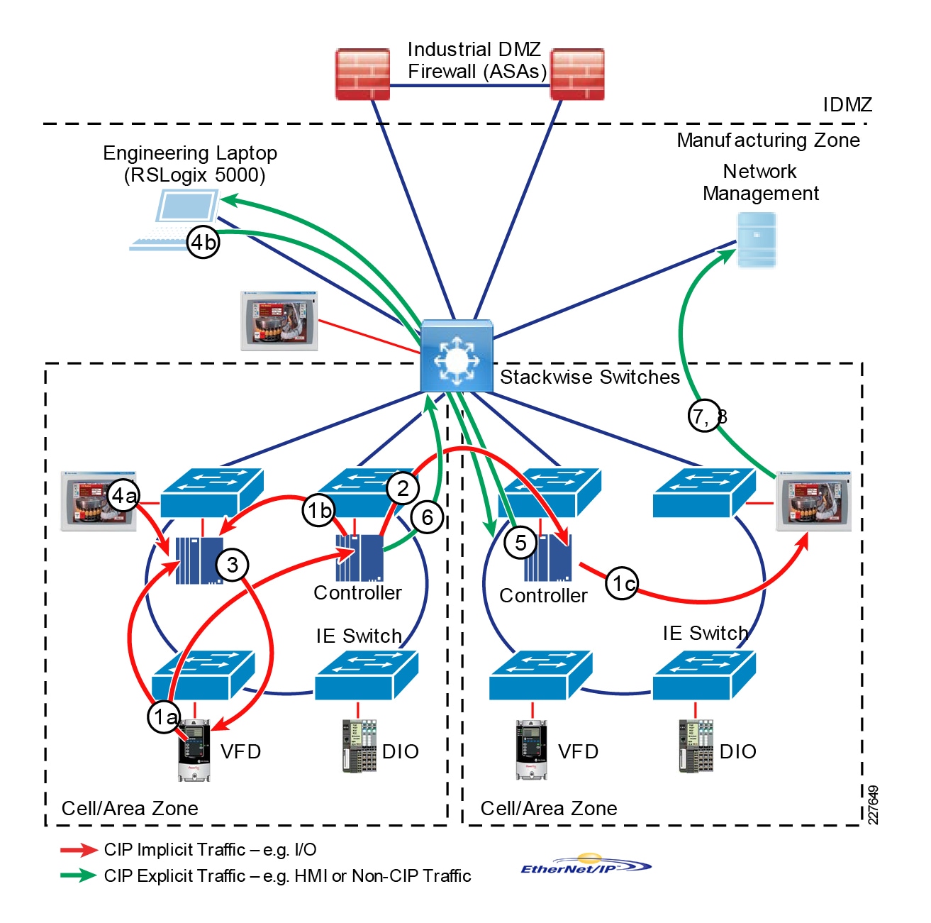
Figure 22 PROFINET Cell/Area Zone Traffic Flows
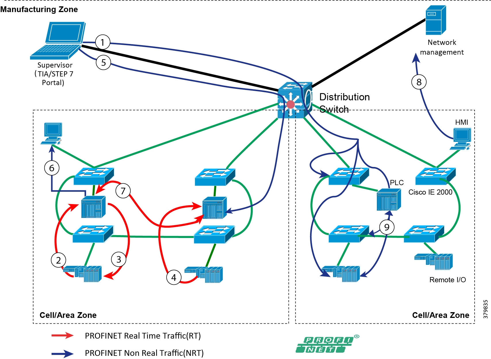
| | | | | | |
| | | | | | |
| | | | | | |
| | | | | | |
| | | | | | |
| | | | | | |
| | | | | | |
| | | | | | |
| | | | | | |
| | | | | | |
Cell/Area Zone Performance and QoS Design
QoS provides classification, prioritization, and preferential forwarding treatment to various traffic flows within the Cell/Area Zone. Dedicated bandwidth and predictable jitter and latency are required by some IACS applications (real-time). QoS can help provide this in the Cell/Area Zone; IACS real-time traffic flows with the highest performance requirements will be given precedence over all traffic types. This prioritization helps to contribute to network performance, assurance, and predictability which is required to ensure ACS application uptime and efficiency and ultimately contribute to OEE.
Traffic types not involving IACS devices also exist within the Cell/Area Zone. In reference to the description of traffic flows in the Cell/Area Zone, Level 3 traffic originating from workstations and servers occurs, such as SNMP and HTTP traffic. An industrial customer may choose to deploy operational support services such as voice or video in the industrial zone on a shared network infrastructure, however this should be evaluated as part of the risk assessment and aligned with a QoS model defined for a converged architecture. In contrast, operational support services can be physically separated from the IACS devices and applications with independent network infrastructures.
Real-time performance and characteristics of the IACS applications should be well understood when designing to provide predictability and consistency in networking performance. As previously stated, the IACS applications and performance are paramount to ensuring uptime, efficiency, and ultimately OEE. A variety of IACS traffic could be deployed within the Cell/Area Zone which have very different network requirements for latency, jitter, and packet loss. Any unpredictability in the network performance causing too much latency or jitter as well as packet loss could cause IACS system errors or a shutdown of equipment. The following tables reference a defined set of requirements for various types of informational and time-critical I/O traffic classes.
IACS Application Real-Time Requirements-Cisco
| Requirement Class | Typical Cycle Time | Typical RPI | Connection Timeout |
|---|---|---|---|
| Information/Process (for example, HMI) | < 1 s | 100 - 250 ms | Product dependent |
| Time critical processes (for example, I/O) | 30 - 50 ms | 20 ms | 4 intervals of RPI, but =100 ms |
| Safety | 10 - 30 ms | 10 ms | 24 - 1000 ms |
| Motion | 500 µs - 5ms | 50 µs - 1 ms | 4 intervals |
| Requirement Class | Typical Cycle Time | Typical RPI | Communication Class |
|---|---|---|---|
| Information/Process | < 1 s | 100 - 250 ms | Non-Real Time (NRT) |
| Process/Discrete | 30 - 50 ms | 20 ms | Real Time (RT) |
Table 10 and Table 11 highlight the differing network characteristics between the various IACS applications that could be deployed in the Cell/Area Zone. The key IACS performance requirements are machine/process cycle times and the Request Packet Interval (RPI), which if not met can cause a connection timeout or shutdown of the equipment/process. These are usually defined as:
■![]() Machine/process cycle times-The processing time in which industrial automation system application makes decisions
Machine/process cycle times-The processing time in which industrial automation system application makes decisions
■![]() I/O update time-The processing time at which input/outputs are sent/received
I/O update time-The processing time at which input/outputs are sent/received
Table 10 and Table 11 also show the network would need to provide higher network performance for time critical versus informational traffic and even higher performance for motion and safety applications or systems. The QoS design for Industrial Automation followed the guidelines and standards outlined by ODVA, Inc. for a QoS Model with Common Industrial Protocol (CIP) and Precision Timing Protocol (PTP) traffic. These are built on the following premises:
■![]() Prioritization for IACS traffic over non-IACS traffic in the Cell/Area Zone if deployed on a shared infrastructure
Prioritization for IACS traffic over non-IACS traffic in the Cell/Area Zone if deployed on a shared infrastructure
■![]() IACS real-time traffic over IACS non-real-time traffic in the Cell/Area Zone
IACS real-time traffic over IACS non-real-time traffic in the Cell/Area Zone
■![]() Within real-time services further differentiation may be required to support higher performance applications such as Safety and Motion.
Within real-time services further differentiation may be required to support higher performance applications such as Safety and Motion.
■![]() QoS deployed plant wide in a consistent manner. Network devices across the plant need to adhere to the same policy.
QoS deployed plant wide in a consistent manner. Network devices across the plant need to adhere to the same policy.
| | | | | |
| | | | | |
| | | | | |
| | | | | |
| | | | I/O | |
| | | | | |
| | | | | |
| | | | | |
Cisco QoS uses a toolset to provide the priority and preferential treatment for the IACS traffic. The key tools used across the platforms for this version of Industrial Automation are:
■![]() Classification and Marking—Classifying or marking the traffic as it enters the network to establish a trust boundary that is used by subsequent QoS tools, such as scheduling. Class maps and policy maps are the mechanism to provide the network classification.
Classification and Marking—Classifying or marking the traffic as it enters the network to establish a trust boundary that is used by subsequent QoS tools, such as scheduling. Class maps and policy maps are the mechanism to provide the network classification.
■![]() Policing and Markdown—Policing tools, known as Policers, determine whether packets are conforming to administratively-defined traffic rates and take action accordingly. Such action could include marking, remarking, or dropping a packet.
Policing and Markdown—Policing tools, known as Policers, determine whether packets are conforming to administratively-defined traffic rates and take action accordingly. Such action could include marking, remarking, or dropping a packet.
■![]() Scheduling (Queuing and Dropping)—Scheduling tools determine how a frame or packet exits a device. Whenever packets enter a device faster than they can exit it, such as with speed mismatches, then a point of congestion or bottleneck can occur. Devices have buffers that allow for scheduling higher priority packets to exit sooner, which is commonly called queueing.
Scheduling (Queuing and Dropping)—Scheduling tools determine how a frame or packet exits a device. Whenever packets enter a device faster than they can exit it, such as with speed mismatches, then a point of congestion or bottleneck can occur. Devices have buffers that allow for scheduling higher priority packets to exit sooner, which is commonly called queueing.
Note: Policing and Markdown is not used in the QoS design for IACS traffic as we do want to impact control traffic.
Classify and mark all traffic at the access point to the network. Devices that are capable of marking the traffic may be connected to the access switches with trusted ports. Devices not capable of marking their network traffic would need to be classified and marked at the access switch and these network ports would be untrusted. The general guidance is to not trust the CoS/DSCP markings entering the access switch and have the access switch classify and mark all the traffic entering the network. This provides a level of assurance and correct classification at the network edge.
Once classified and in the network, the uplink and outbound ports on the network switches can be trusted and configured to schedule traffic according to the QoS profile. Figure 23 highlights the trusted versus untrusted description.
| | | | | | | | | | ||||
| | | | | | | | | | ||||
| | | | | | | | | | | | | |
| | | | | | | | | | ||||
| | | | ||||||||||
| | | | | | | |||||||
| | | | | | ||||||||
| | | | | | | | | |||||
Figure 23 QoS Trust Boundaries
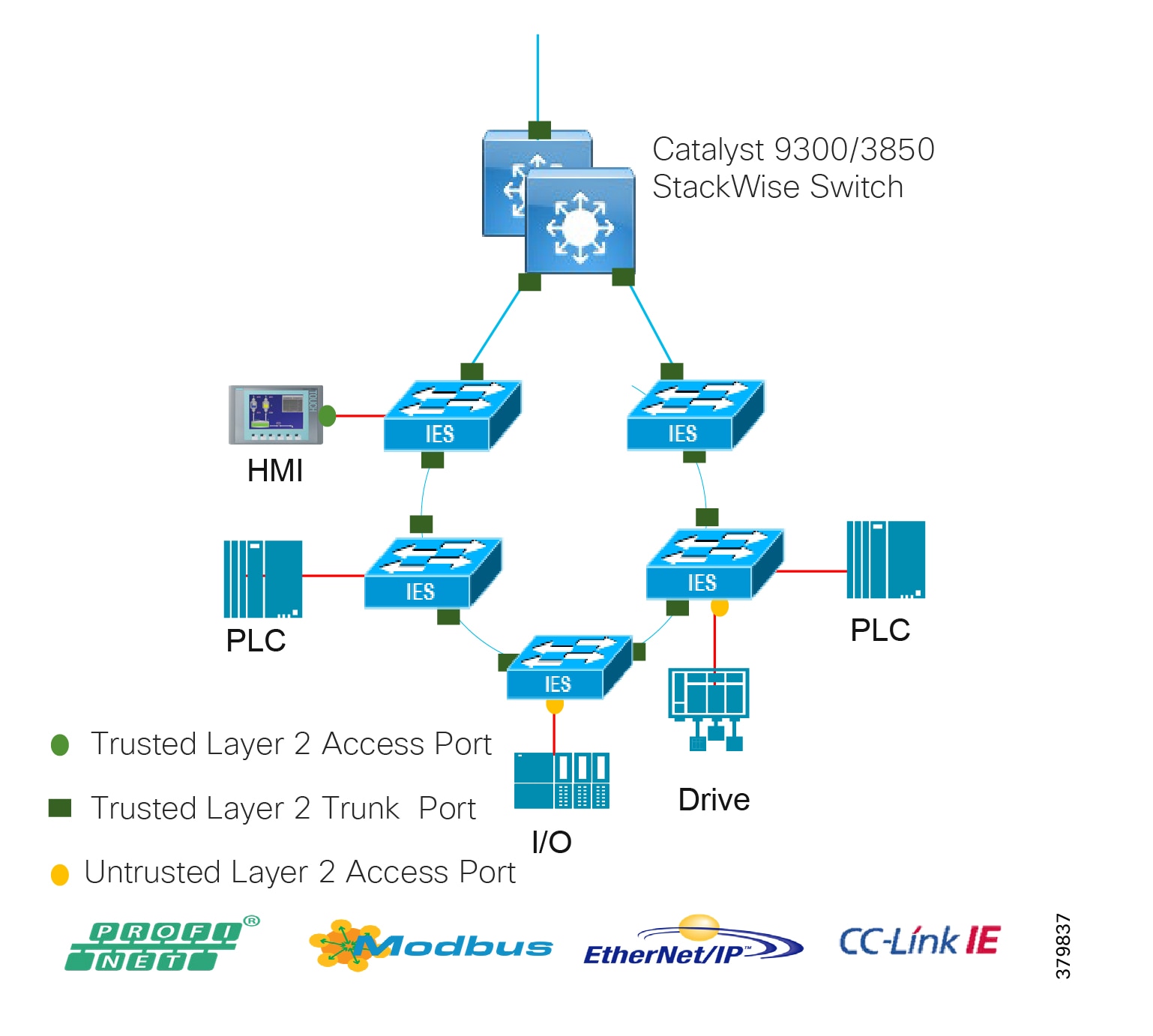
Ingress and egress queues on all the switches in the Cell/Area Zone including the distribution switches are serviced using the shared round robin mechanism. The classified traffic is mapped to specific ingress and egress queues to provide preferential treatment and avoid packet loss to real-time traffic. Bandwidth can be assigned to the queues to ensure and guarantee that a level of service is maintained during times of network congestion, thus keeping to the availability and assurance required for certain applications. Within the ODVA, Inc. model, a priority queue is assigned to the most critical traffic in the QoS design, which ensures strict prioritization of this queue.
Table 14 and Table 15 shows the QoS settings for the switches in the design that have been tested as part of Industrial Automation. These settings are taken from the ODVA, Inc.QoS recommended settings for CIP traffic.
| | | | | | |
| | | | | | |
| | | | | | |
| | | | | | | |
| | | | | | | |
| | | | | | | |
| | | | PTP Management, CIP Implicit I/O, Network Control, and Voice data | | | |
| | | | | | | |
Configuration details and an in-depth description of the scheduling mechanisms for all the switches can be found in Quality of Service. The switches evaluated in this round of testing included the Cisco IE 2000, Cisco IE 4000, Cisco IE 3200, Cisco IE 3400, and the Cisco Catalyst 9300 and Cisco Catalyst 3850.
Multicast Management in the Cell/Area Zone and ESP
Networking switches within the Cell/Area Zone should facilitate the support of multicast as it is used by some of the IACS protocols. In general, the multicast traffic at Cell/Area Zone does not go beyond Layer 2. Mechanisms are used in some of the protocols to prevent passing routed boundaries, such as keeping the TTL at 1 within the IP packet. Within the context of a Layer 2 multicast network, Internet Group Management Protocol (IGMP) snooping is used to manage and control the multicast traffic. Figure 24 highlights the components and functions within the Cell/Area Zone for supporting IACS traffic deployed with multicast.
Figure 24 Cell/Zone Multicast
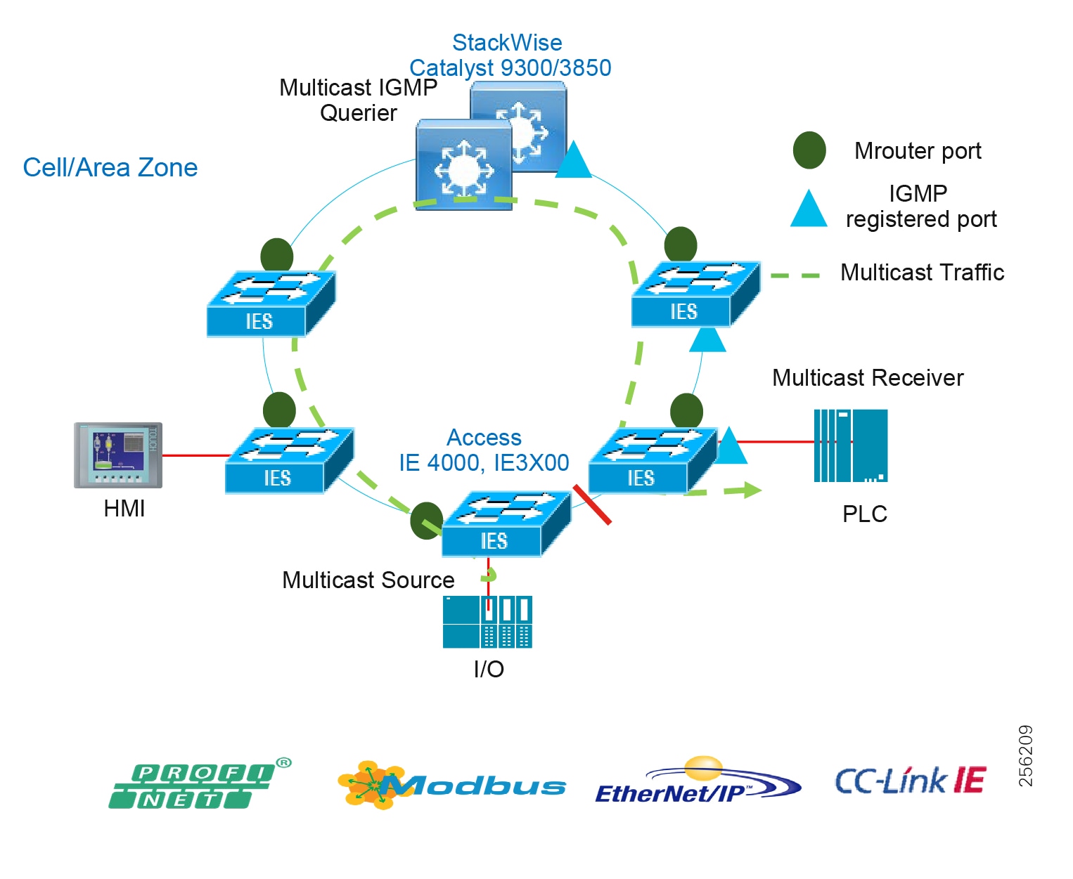
■![]() IGMP Snooping—With IGMP snooping in the Layer 2 switches, the switch is able to restrict switching of multicast packets out to only those ports that require it.
IGMP Snooping—With IGMP snooping in the Layer 2 switches, the switch is able to restrict switching of multicast packets out to only those ports that require it.
■![]() IGMP Querier—Keeps track of the multicast group membership. A querier is a network device that sends query messages to discover which network devices are members of a given multicast group.
IGMP Querier—Keeps track of the multicast group membership. A querier is a network device that sends query messages to discover which network devices are members of a given multicast group.
■![]() Multicast router (Mrouter) port—The port facing the IGMP querier or where the multicast and query traffic will be received. A snooping switch should forward IGMP membership reports only to those ports to where multicast routers are attached or where IGMP queries are to be sent (querier).
Multicast router (Mrouter) port—The port facing the IGMP querier or where the multicast and query traffic will be received. A snooping switch should forward IGMP membership reports only to those ports to where multicast routers are attached or where IGMP queries are to be sent (querier).
Recommendations for Deploying Multicast in the Cell/Area Zone
■![]() Enable IGMP snooping and querier on all the industrial Ethernet switches as well as the distribution switch/router. Do not change any of the IGMP snooping default settings.
Enable IGMP snooping and querier on all the industrial Ethernet switches as well as the distribution switch/router. Do not change any of the IGMP snooping default settings.
■![]() Configure the IGMP querier on the distribution switch or central to the Cell/Area Zone topology. When multiple IGMP queriers are on a VLAN, the IGMP protocol calls for the querier with the lowest IP address to take over the querier function. Therefore, the distribution switch should have the lowest IP address in the subnet.
Configure the IGMP querier on the distribution switch or central to the Cell/Area Zone topology. When multiple IGMP queriers are on a VLAN, the IGMP protocol calls for the querier with the lowest IP address to take over the querier function. Therefore, the distribution switch should have the lowest IP address in the subnet.
Availability
Availability of the industrial automation process affects the business directly and is therefore a critical component. Ensuring the uptime of the IACS applications requires a robust, resilient network. This section provides network design to support availability for IACS applications with platform protocol and path redundancy.
Within the QoS and performance section, RPI and cycle time were key metrics that the network needed to be able to support. The cycle time is the critical requirement for network availability. The network needs to recover within the cycle time to prevent any IACS application timeouts which could cause a shutdown of the process. If the network can recover from a failure within the cycle time, then theoretically the IACS application should continue to operate. With this in mind Table 16 provides a view of target network convergence times for the IACS.
| Requirement Class | Target Cycle Time | Target RPI | Target Network Convergence |
|---|---|---|---|
| Information/Process (for example, HMI) | < 1 s | 100 - 250 ms | < 1 sec |
| Time critical processes (for example, I/O) | 30 - 50 ms | 20 ms | < 100 ms |
| Safety | 10 - 30 ms | 10 ms | < 24 ms |
| Motion | 500 µs - 5ms | 50 µs - 1 ms | < 1ms |
Media Considerations
Media plays a large part in contributing to the convergence times for failures in the network. Copper Ethernet links contribute to larger convergence times than fiber and take longer to detect the failure without any supplementary keepalive mechanism. This is reflected in some of the convergence tests that were conducted. In topologies with Cisco IE 3x00 switches, REP Fast can be used to improve overall convergence time, especially for copper connections; when a link failure occurs, the REP Fast convergence time is comparable between fiber and copper.
The specific Cisco Catalyst 9300 platform aggregating the rings was the Cisco Catalyst 9300-48P. At the time of testing this platform only supported copper downlinks. A 1/10 Gbps uplink module was evaluated to provide fiber media convergence numbers. Copper downlinks were also evaluated in certain scenarios.
Distribution Switch Resiliency
This section describes the resiliency options validated for industrial automation at the distribution switch in the Cell/Area Zone boundary.
■![]() Cisco StackWise-480
Cisco StackWise-480
■![]() Hot Standby Redundancy Protocol
Hot Standby Redundancy Protocol
Figure 25 Distribution Switch Resiliency
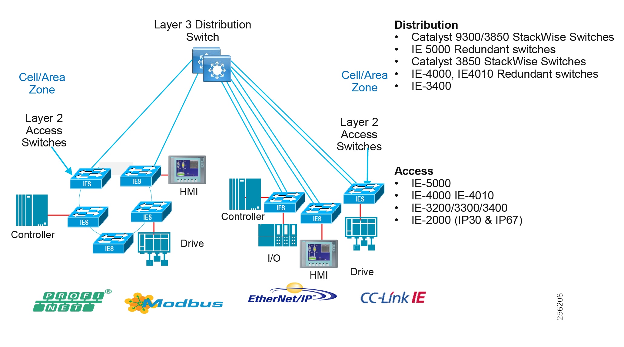
Cisco StackWise-480
The Cisco Catalyst 3850 and Cisco Catalyst 9300 supports StackWise-480 configurations to provide platform resiliency at the distribution layer. A switch stack can have up to eight stacking-capable switches connected through their StackWise-480 ports. The stack members work together as a unified system. Layer 2 and Layer 3 protocols present the entire switch stack as a single entity to the network.
A switch stack always has one active switch and one standby switch. The active switch will provide control of the management plane for the stack. If the active switch becomes unavailable, the standby switch assumes the role of the active switch and keeps the stack operational. In this guide the switch stacks were validated with two switches to provide the Cell/Area Zone distribution switch resiliency.
For more information on switch stack configuration and features for the Cisco Catalyst 9300 see:
https://www.cisco.com/c/en/us/td/docs/switches/lan/catalyst9300/software/release/16-9/configuration_guide/stck_mgr_ha/b_169_stck_mgr_ha_9300_cg/managing_switch_stacks.html
Hot Standby Redundancy Protocol
Hot Standby Redundancy Protocol (HSRP) is an alternative to StackWise-480 for the distribution switch. HSRP provides high availability through redundancy for IP traffic from hosts on networks. In a group of router interfaces, the active router sends packets; the standby router takes over the routing duties when an active router fails or when preset conditions are met. For the CVD, two Layer 3-enabled switches were deployed for HSRP scenarios, one active and one standby.
StackWise Virtual
Another platform resiliency option at the distribution layer is StackWise Virtual. The Cisco Catalyst 9500 as well as the Cisco IE 5000 switches support StackWise Virtual, where two switches are connected through redundant 10 or 40 gigabit links and operate as a single switch with active and standby nodes. Much like StackWise-480, Layer 2 and Layer 3 functions operate from the single "virtual" entity and the control, management, and data planes are integrated. The limitation for StackWise Virtual is the lack of support for REP, RSPAN, and SDA, therefore StackWise Virtual configurations were not validated for this release.
Path Redundancy
Network path redundancy provides alternative paths through a network under equipment or link failure. Within the Cell/Area Zone, this network redundancy is provided on all uplinks from the edge switching platforms using a star or a ring topology. A resiliency protocol needs to be deployed to prevent loops within the redundant links; loops are created in Layer 2 networks when there are multiple active paths to the same destination. Resilient Ethernet Protocol (REP), Mdia Redundancy Protocol (MRP), PRP, and HSR can prevent frames from looping within a ring topology and EtherChannel or Flex Links within a star topology.
■![]() Redundancy for star topologies—EtherChannel or Flex Links
Redundancy for star topologies—EtherChannel or Flex Links
■![]() Redundancy for ring topologies—MRP, REP, and HSR
Redundancy for ring topologies—MRP, REP, and HSR
■![]() Redundancy for multiple, independent networks—PRP
Redundancy for multiple, independent networks—PRP
Redundant Star Topology
EtherChannel
EtherChannel groups multiple physical Ethernet links into a single logical link between two switches. Traffic traversing the logical link between two switches is load balanced over the physical links. If a physical link fails within the EtherChannel, then the traffic is redistributed across the other available links in the EtherChannel. Although not strictly a resiliency protocol, the EtherChannel can be deployed to provide resiliency when there are multiple links between the same two switches. In industrial automation this is configured as an option for redundant star configurations when connecting between an access switch (for example, Cisco IE 4000) and the distribution switches running StackWise.
Figure 26 Cell/Area Zone Redundant Star Topology
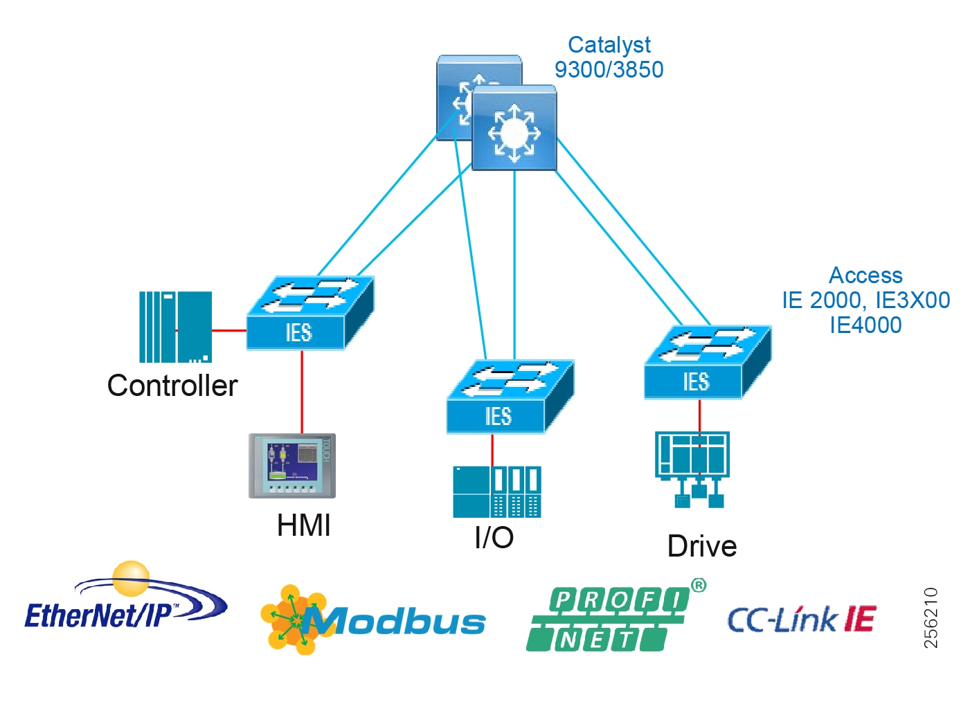
Flex Links
Flex Links are a pair of a Layer 2 interfaces (switch ports or port channels), where one interface is configured to act as a backup to the other. This feature provides an alternative solution to the Spanning Tree Protocol (STP) and is deployed between an access switch and a distribution switch. The active link is used to forward and receive frames and the standby link does not forward or receive frames, but is in the up/up state. When a failure is detected on the active link, the standby link moves to active and all MAC addresses and multicast entries move to the standby link. On restoration of the failed link it will again become the standby link.
Figure 27 Cell/Area Zone Flex Links
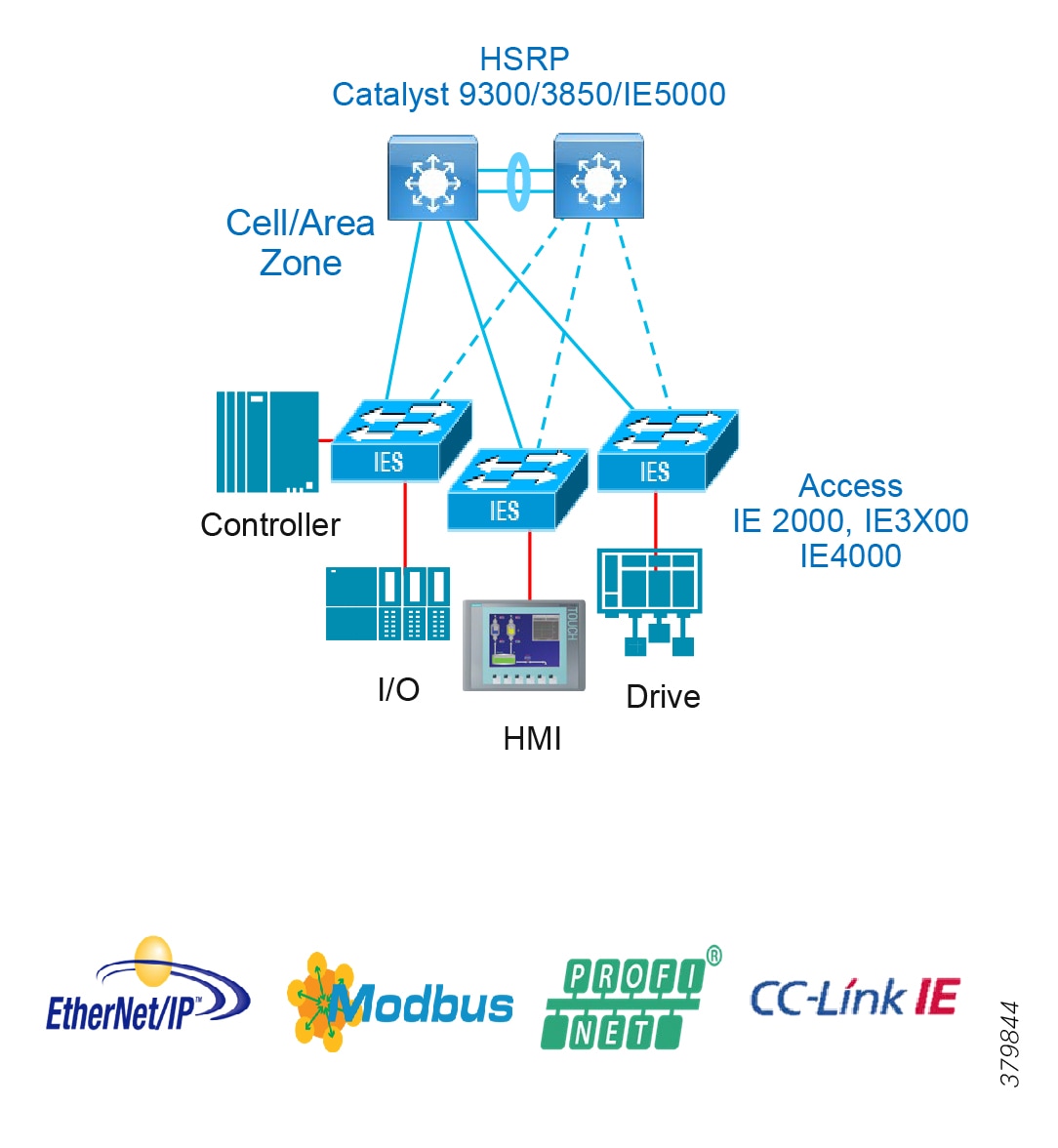
Note: The Cisco IE 3200, Cisco IE 3300, and Cisco IE 3400 switches do not support Flex links in the software used for this CVD.
Redundant Star Design and Validation
The following figures detail the various scenarios covered for the industrial automation and the convergence times.
Cisco Catalyst 9300 and Cisco Catalyst 3850 switches were evaluated with the Cisco IE 3200/Cisco IE 3400 and Cisco IE 4000 switches in a redundant star configuration with EtherChannel. Only EtherChannel was evaluated for Cisco IE 3200/Cisco IE 3400. Figure 28 highlights the validation scenario.
Figure 28 Redundant Star Design and Validation
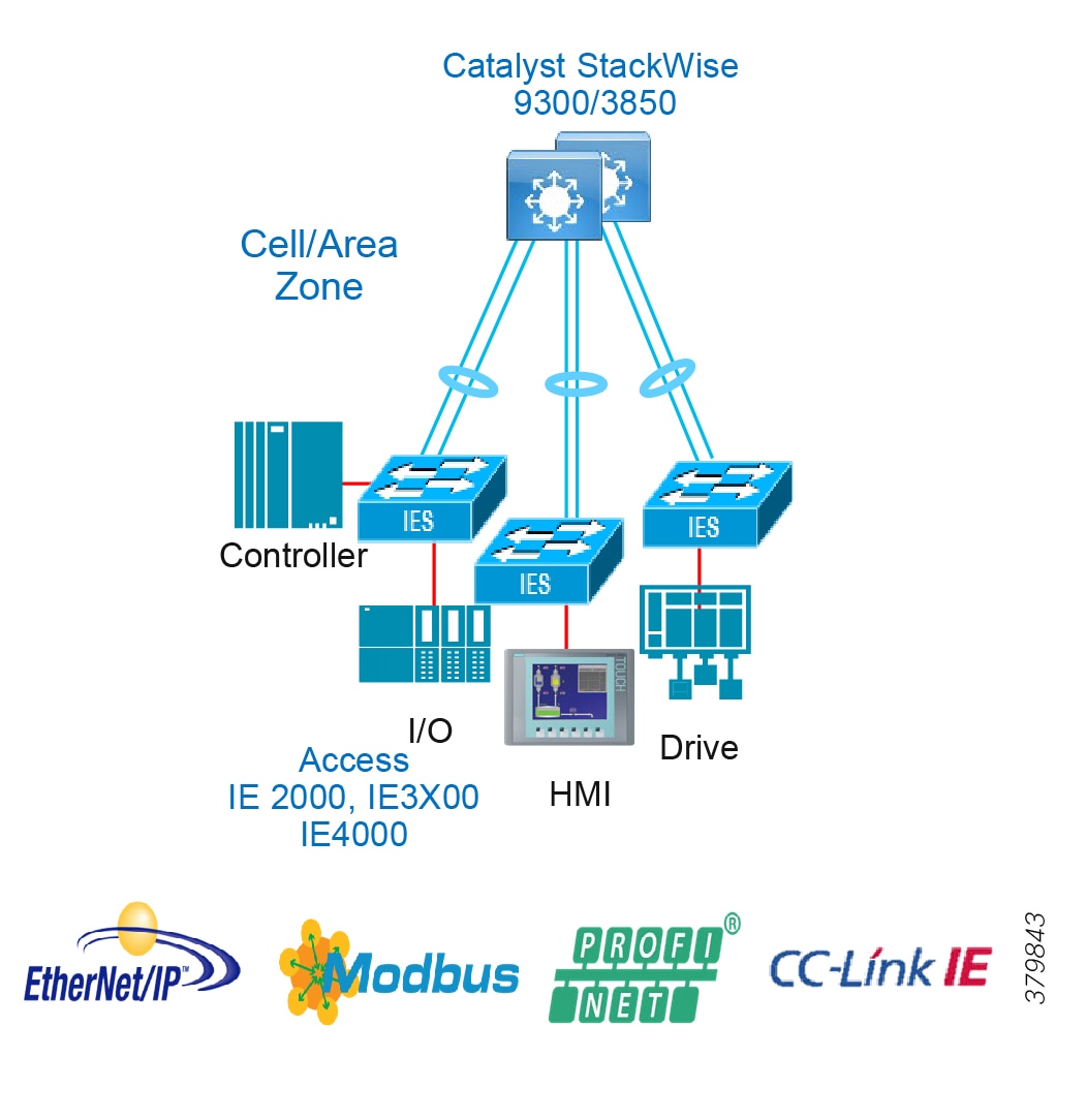
Table 17 and Table 18 provide details of the convergence results for multiple types of failures. Link disruptions refer to a single link failure in the ring. Switch failures refer to a primary distribution switch failure where the backup switch would assume the active role. Multiple link and switch failures were conducted where the maximum and average convergence times were recorded. Simulated traffic and real IACS devices were used during validation. The scenario was run with 250 MAC addresses, 200 multicast groups, and inter- and intra-VLAN traffic.
| | | | | | |||
| | | | | | | ||
| | | | | | | | |
| | | | | | | | |
| | | | | | | | |
| | | | | | | | |
| | | | | | | | |
| | | | | | | | |
| | | | |
| | | ||
| | | | |
| | | | |
| | | | |
| | | | |
| | | | |
| | | | |
Result Considerations
The convergence for link failures using the Cisco Catalyst 9300 copper downlinks with Cisco IE 3200/Cisco IE 3400 were much higher than with the Cisco IE 4000.
Fiber testing for the Cisco IE 3200/Cisco IE 3400 was much improved in these scenarios with both the Cisco Catalyst 3850 and Cisco Catalyst 9300 as the distribution switch.
■![]() With Cisco Catalyst 9300 as the distribution switch, Cisco IE 3200/Cisco IE 3400 is not recommended with copper media for IACS applications with outliers that may cause connection timeouts.
With Cisco Catalyst 9300 as the distribution switch, Cisco IE 3200/Cisco IE 3400 is not recommended with copper media for IACS applications with outliers that may cause connection timeouts.
■![]() With the Cisco Catalyst 9300 the distribution switch failure may cause higher convergence time for Layer 2 multicast traffic (238ms) and cause connection timeouts for IACS applications that use multicast. The applications can be tuned to accommodate or potentially not use multicast for the application.
With the Cisco Catalyst 9300 the distribution switch failure may cause higher convergence time for Layer 2 multicast traffic (238ms) and cause connection timeouts for IACS applications that use multicast. The applications can be tuned to accommodate or potentially not use multicast for the application.
Ring Resiliency Protocols
REP
REP is a Cisco proprietary protocol that provides an alternative to STP to control network loops, handle link failures, and improve convergence time. REP runs a single redundancy instance per segment or physical ring. One REP segment is a chain of ports connected to each other and configured with a segment ID. Each segment consists of standard (non-edge) segment ports and two user-configured edge ports. A switch can have no more than two ports that belong to the same segment and each segment port can have only one external neighbor.
Each end of a network segment terminates at a neighboring Cisco IE access switch or distribution switch. The port where the segment terminates is called the edge port. Figure 29 illustrates a typical REP segment deployed in Industrial Automation.
Figure 29 REP Overview
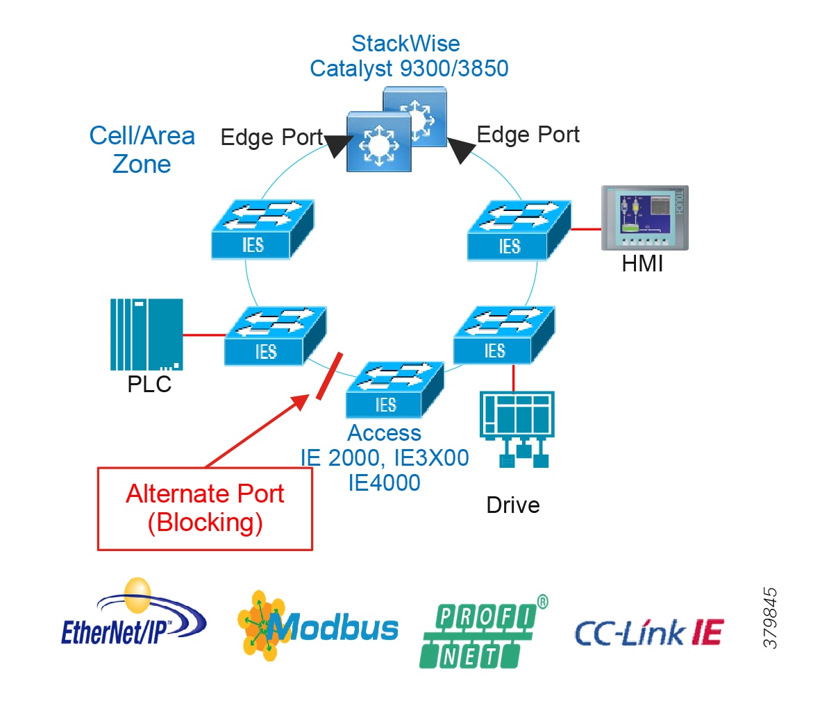
Loop prevention in the ring is maintained with one port in the segment being in a blocked state, also known as the alternate port. If a failure in the segment is detected, then the alternate port will move to a forwarding state allowing traffic to traverse the alternate path avoiding the network failure.
REP Basic Operation and Failover
Any REP-enabled node can trigger a failure notification within a segment. Link failures do not rely on there being a ring primary node to update all other nodes of the failure, as is the case with STP. REP nodes maintain neighbor adjacencies with a link status layer which sends hello packets to be acknowledged. Segment failures in the ring are discovered through loss of signal or loss of connectivity (no response to the hellos). When a node detects a failure it will send link failure notifications to its REP peers. To maintain fast convergence in industrial environments, Cisco REP uses a fast failure notification, propagating the notifications through the use of a reserved multicast address. The notification is forwarded so that each node in the segment is notified immediately. This will move the alternate port to a forwarding state and cause flushing of the MAC address tables of all switches on the segment.
Figure 30 REP Blocking Port Removed Under Failure
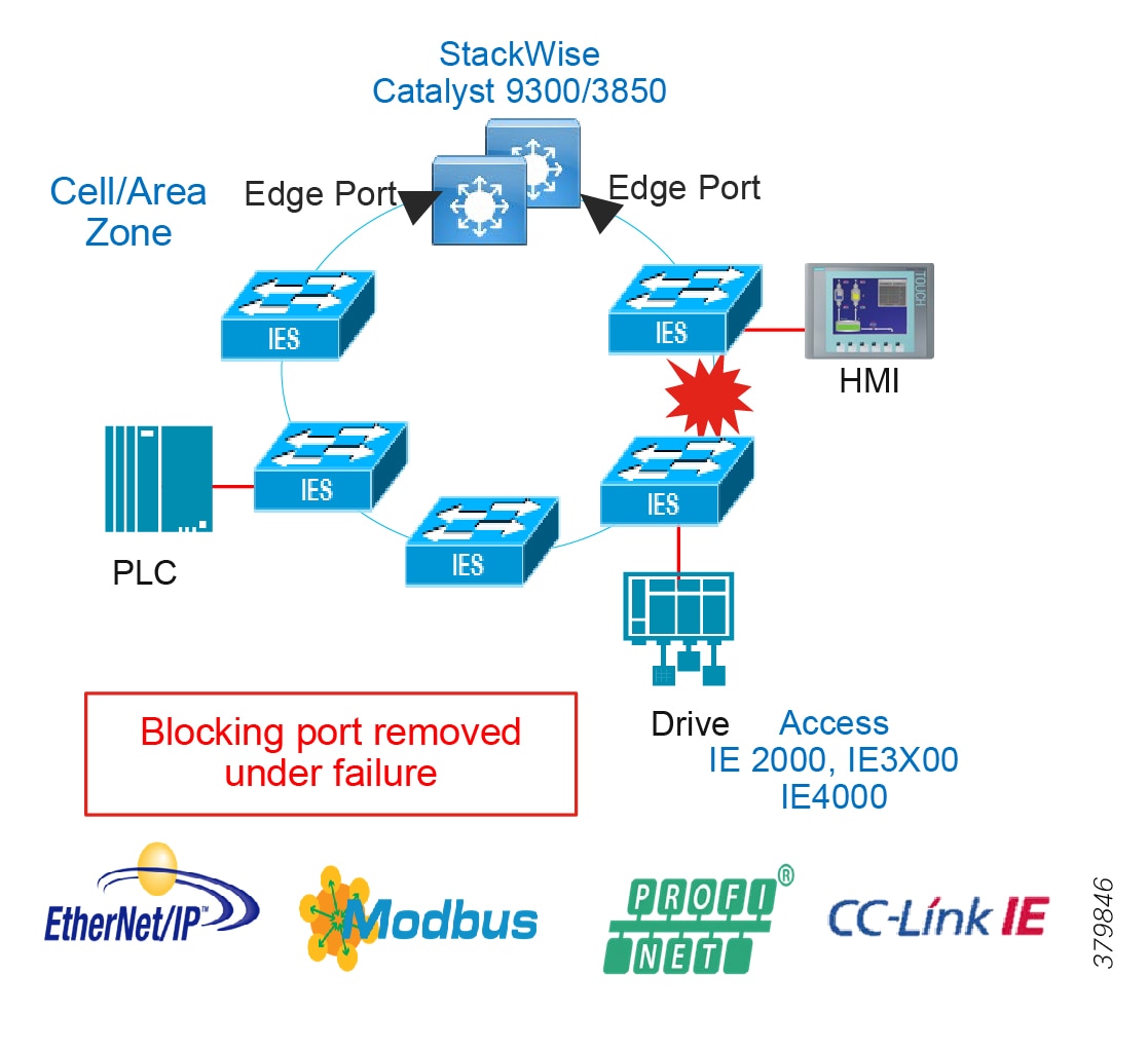
Figure 31 REP Alternate Port Post Failure
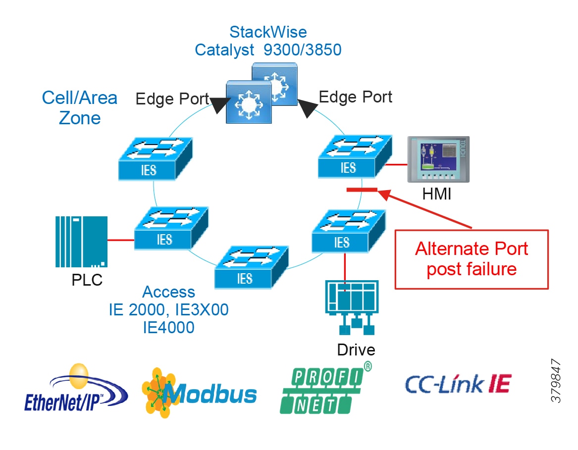
Upon restoration of the failure the point of failure will become the new alternate port which avoids disruption of the ring. If a known desired state is required after failure is required then preemption can be configured to position the blocked port to a specific location in the ring, however this preemption event would trigger a disruption of the ring.
REP Topologies Design and Recommendations
| | | | | | |||
| | | | | | | ||
| | | | | | | | |
| | | | | | | | |
| | | | | | | | |
| | | | | | | | |
| | | | | | | | |
| | | | | | | | |
Result Considerations
■![]() Convergence was validated for Layer 2 traffic within a VLAN and Layer 3 traffic between VLANs in the same ring.
Convergence was validated for Layer 2 traffic within a VLAN and Layer 3 traffic between VLANs in the same ring.
■![]() Link disruptions refer to a single link failure in the ring. Switch failures refer to power interruption of a single switch at a time; distribution members and IE switches were reloaded during testing.
Link disruptions refer to a single link failure in the ring. Switch failures refer to power interruption of a single switch at a time; distribution members and IE switches were reloaded during testing.
■![]() Simulated traffic and real IACS devices were used during validation.
Simulated traffic and real IACS devices were used during validation.
■![]() The scenario was run with 250 MAC addresses, 200 multicast groups, and inter- and intra-VLAN traffic.
The scenario was run with 250 MAC addresses, 200 multicast groups, and inter- and intra-VLAN traffic.
■![]() Three REP rings:
Three REP rings:
–![]() Mixed ring—Cisco IE 3200, Cisco IE 3300, Cisco IE 3400, and Cisco IE 4000 (12 nodes)
Mixed ring—Cisco IE 3200, Cisco IE 3300, Cisco IE 3400, and Cisco IE 4000 (12 nodes)
–![]() IE 3x00 ring—Cisco IE 3200, Cisco IE 3300, and Cisco IE 3400 (11 nodes)
IE 3x00 ring—Cisco IE 3200, Cisco IE 3300, and Cisco IE 3400 (11 nodes)
–![]() IE 3400H ring—Cisco IE 3400H (4 nodes)
IE 3400H ring—Cisco IE 3400H (4 nodes)
REP Ring with Cisco Catalyst 3850/Cisco Catalyst 9300 in Distribution
Recommendations for this topology:
■![]() It is recommended to use fiber links since it provides faster convergence than copper links.
It is recommended to use fiber links since it provides faster convergence than copper links.
■![]() When using StackWise for distribution with a REP ring it is a good practice to locate the alternate port in between access switches to achieve higher Layer 3 convergence in case of primary stack member power failure.
When using StackWise for distribution with a REP ring it is a good practice to locate the alternate port in between access switches to achieve higher Layer 3 convergence in case of primary stack member power failure.
Figure 32 REP Ring with Cisco Catalyst 3850/Cisco Catalyst 9300 in Distribution
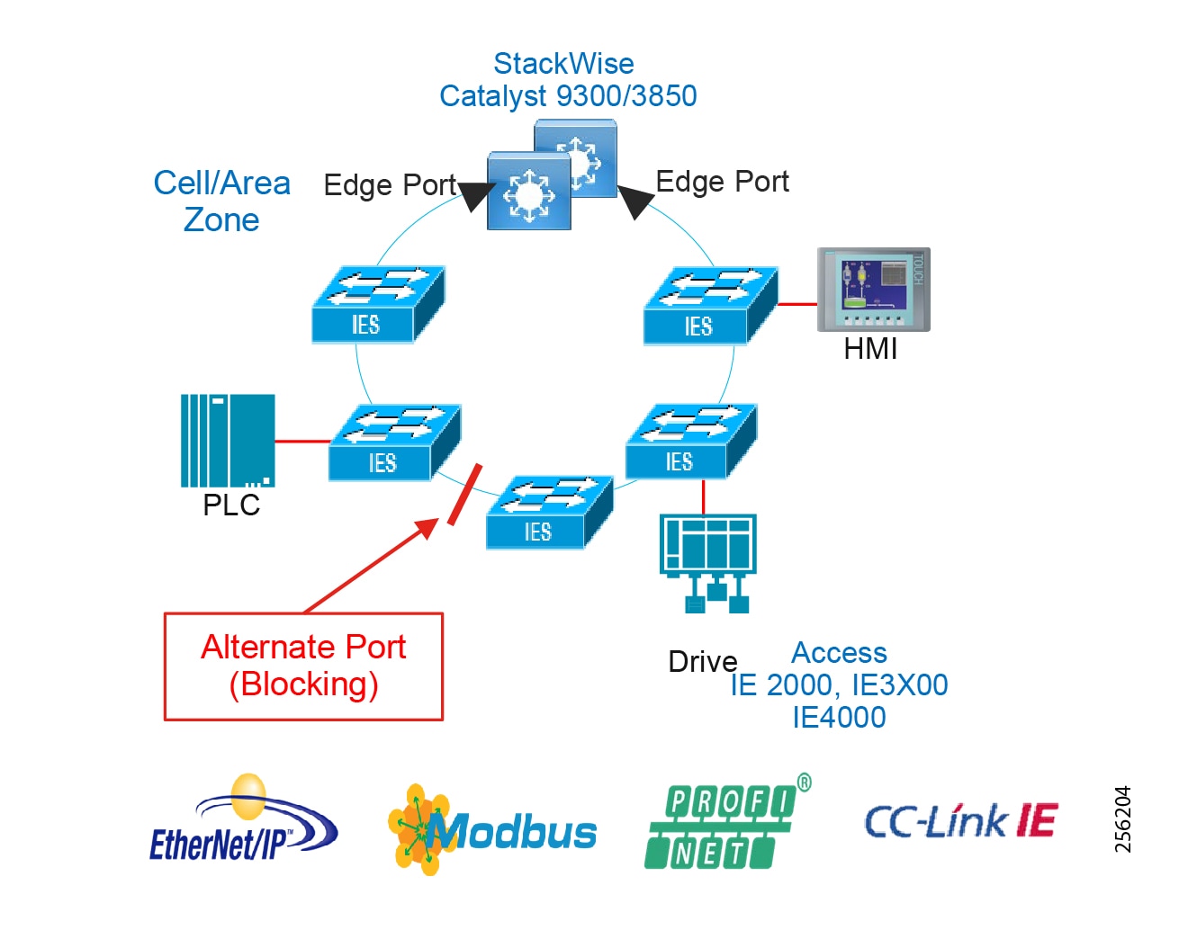
Table 20 summarizes convergence results during validation.
| | | | | | |||
| | | | | | | ||
| | | | | | | | |
| | | | | | | | |
| | | | | | | | |
| | | | | | | | |
| | | | | | | | |
| | | | | | | | |
Result Considerations
■![]() Convergence was validated for Layer 2 traffic within a VLAN and Layer 3 traffic between VLANs in the same ring.
Convergence was validated for Layer 2 traffic within a VLAN and Layer 3 traffic between VLANs in the same ring.
■![]() Link disruptions refer to a single link failure in the ring. Switch failures refer to power interruption of a single switch at a time; distribution members and IE switches were reloaded during testing.
Link disruptions refer to a single link failure in the ring. Switch failures refer to power interruption of a single switch at a time; distribution members and IE switches were reloaded during testing.
■![]() Three REP rings were evaluated with the following switches:
Three REP rings were evaluated with the following switches:
–![]() Mixed ring—Cisco IE 3200, Cisco IE 3300, Cisco IE 3400, and Cisco IE 4000 (12 nodes)
Mixed ring—Cisco IE 3200, Cisco IE 3300, Cisco IE 3400, and Cisco IE 4000 (12 nodes)
–![]() IE3x00 ring—Cisco IE 3200, Cisco IE 3300, and Cisco IE 4000 (11 nodes)
IE3x00 ring—Cisco IE 3200, Cisco IE 3300, and Cisco IE 4000 (11 nodes)
–![]() IE3400H ring—Cisco IE 3400H (4 nodes)
IE3400H ring—Cisco IE 3400H (4 nodes)
■![]() The Cisco Catalyst 9300 distribution node contained two Stack members.
The Cisco Catalyst 9300 distribution node contained two Stack members.
■![]() Simulated traffic and real IACS devices were used during validation. The scenario was run with 250 MAC addresses, 200 multicast groups, and inter- and intra-VLAN traffic.
Simulated traffic and real IACS devices were used during validation. The scenario was run with 250 MAC addresses, 200 multicast groups, and inter- and intra-VLAN traffic.
The Cisco Catalyst 9300 distribution StackWise configuration with Cisco IE 3x00 access switches should be considered as the best choice for REP deployments for IACS environments, though considerations should be given to the outlier Max results for convergence which could cause a connection timeout for IACS applications.
REP Fast
The REP Fast feature supported on the Cisco IE 3x00 switches follows the same functionality as REP but improves failure detection time among the participating switches. The switch executes two timers for each REP Fast interface to determine successful transmission; the first timer runs every three milliseconds as the switch sends a beacon frame to the neighbor node. If the frame is received, the timer is reset. If the frame is not received, the second timer begins and lasts for ten milliseconds. If the frame is still not received, the switch sends a link down notification. The REP Fast convergence specification is 50 milliseconds, whereas traditional REP ranges from 50-250 milliseconds.
The Cisco IE 3x00 series switches support REP Fast for copper and fiber and both media produce similar link failure convergence times. In addition, REP and REP Fast can be used in the same ring to connect Cisco IE 3x00 switches with other models that do not support REP Fast. This validation of REP Fast was done with a hybrid REP and REP Fast ring, using traditional REP to connect the Cisco IE 3x00 switches to the respective distribution switches.
Figure 33 REP and REP Fast Ring with Cisco Catalyst 9300 in Distribution
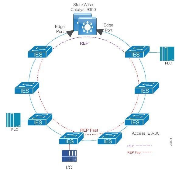
| | | | | ||
| | | | | ||
| | | | | | |
| | | | | | |
| | | | | | |
| | | | | | |
| | | | | | |
| | | | | | |
Figure 34 REP and REP Fast Ring with Cisco IE 5000 in Distribution
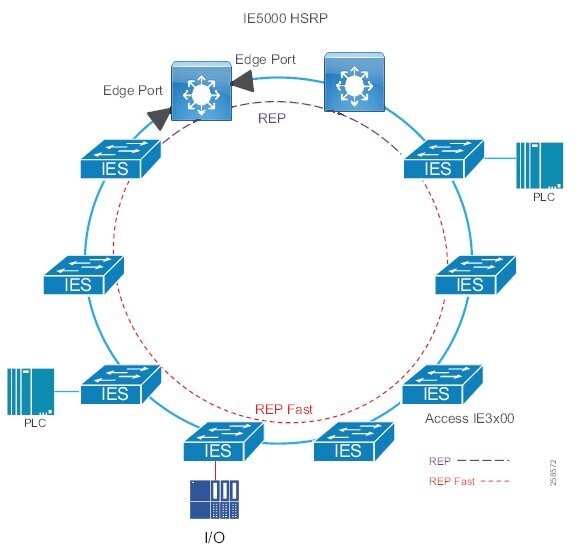
| | | | | ||
| | | | | ||
| | | | | | |
| | | | | | |
| | | | | | |
| | | | | | |
| | | | | | |
| | | | | | |
Result considerations:
■![]() The two rings tested contained IE switches of the following types:
The two rings tested contained IE switches of the following types:
–![]() IE 3x00 (11 nodes): Cisco IE 3200, Cisco IE 3300, and Cisco IE 3400
IE 3x00 (11 nodes): Cisco IE 3200, Cisco IE 3300, and Cisco IE 3400
–![]() Cisco IE 3400H (four nodes)
Cisco IE 3400H (four nodes)
■![]() Convergence was validated for Layer 2 traffic within a VLAN and Layer 3 traffic between VLANs in the same ring.
Convergence was validated for Layer 2 traffic within a VLAN and Layer 3 traffic between VLANs in the same ring.
■![]() Link disruptions refer to a single link failure in the ring. Link failures were conducted at varying points in the ring in both the REP and REP Fast areas. Switch failures refer to power interruption of a single switch at a time; distribution members and IE switches were reloaded during testing.
Link disruptions refer to a single link failure in the ring. Link failures were conducted at varying points in the ring in both the REP and REP Fast areas. Switch failures refer to power interruption of a single switch at a time; distribution members and IE switches were reloaded during testing.
■![]() Simulated traffic and real IACS devices were used during validation.
Simulated traffic and real IACS devices were used during validation.
■![]() The scenario was run with 250 MAC addresses, 200 multicast groups, and inter- and intra-VLAN traffic.
The scenario was run with 250 MAC addresses, 200 multicast groups, and inter- and intra-VLAN traffic.
Parallel Redundancy Protocol (Rings or Non-Rings)
PRP is defined in the International Standard IEC 62439-3 and is deployed in utility substations but could be deployed in manufacturing and plant-based environments that require lossless redundancy for their IACS applications. PRP supports PTP, however PRP utilizes two independent LANs which may be more expensive to implement than HSR, which is ring based.
PRP is designed to provide hitless redundancy (zero recovery time after failures) in Ethernet networks. PRP provides redundancy by connecting to two independent parallel networks (LAN-A and LAN-B) with two separate interfaces at the access or bridging switch. The device connecting to the two independent networks is known as the Dual Attached Node (DAN). This DAN will now have redundant paths to all other DANs in the network.
The DAN sends two packets simultaneously through its two network interfaces to the destination node. A redundancy control trailer (RCT), which includes a sequence number, is added to each frame to help the destination node distinguish between duplicate packets. When the destination DAN receives the first packet successfully, it removes the RCT and consumes the packet and the second packet is discarded. If a failure occurs in one of the paths then the packet will be received on the other network and lossless redundancy is achieved. Lossless redundancy will not be achieved in the unlikely event that both LAN-A and LAN-B have failures at the exact same time. Redundant power is also recommended.
Figure 35 PRP Overview
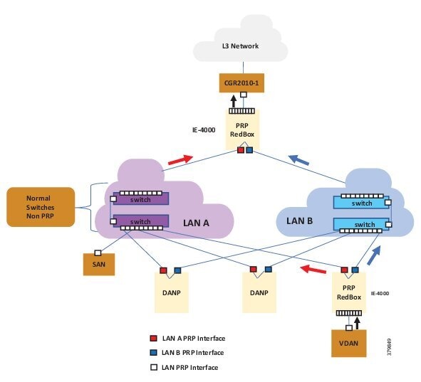
A Redundancy Box (RedBox) is deployed when an end node does not support two network interfaces and PRP redundancy. The RedBox provides the DAN functionality for devices connecting to it. This is the role of the Cisco IE 4000 or Cisco IE 4010 and Cisco IE 5000 in a PRP redundancy deployment. The node behind a RedBox appears for other nodes like a DAN and is known as a Virtual DAN (VDAN).
The last node in a non-redundant node that only connects to a single network. This node would connect to either LAN-A or LAN-B and is known as a Single Attached Node (SAN).
PRP is not concerned with the topology of the independent networks, however the networks should be of a similar configuration so that packet delay is consistent between the two. Therefore, LAN-A and LAN-B can use ring based or star topologies for the deployments as long as both LAN-A and LAN-B use the same topology.
PRP Mixed Traffic and Supervisory Frames
Traffic egressing the RedBox PRP channel group can be mixed, that is, destined to either SANs (connected only on either LAN-A or LAN-B) or DANs. To avoid duplication of packets for SANs, the switch learns source MAC addresses from received supervision frames for DAN entries and source MAC addresses from non-PRP (regular traffic) frames for SAN entries and maintains these addresses in the node table. When forwarding packets out the PRP channel to the SAN MAC addresses, the switch looks up the entry and determines which LAN to send to rather than duplicating the packet.
A RedBox with VDANs needs to send supervisory frames on behalf of those VDANs. For traffic coming in on all other ports and going out PRP channel ports, the switch learns source MAC addresses, adds them to the VDAN table, and starts sending supervisory frames for these addresses. Learned VDAN entries are subject to aging.
PTP over PRP
Precision Time Protocol (PTP) can operate over Parallel Redundancy Protocol (PRP) on Cisco IE 4000, Cisco IE 4010, and Cisco IE 5000 switches. PRP provides high availability through redundancy for PTP. For a description of PTP and its implementation for this phase of industrial automation, see the PTP design for PRP.
For more information on PRP and its features see:
https://www.cisco.com/c/en/us/td/docs/switches/lan/industrial/software/configuration/guide/b_prp_ie4k_5k.html
PRP Summary
■![]() Lossless Redundancy over two parallel networks (LAN A and LAN B)
Lossless Redundancy over two parallel networks (LAN A and LAN B)
■![]() LAN A and B switches do not have to understand PRP protocol and can support any topology.
LAN A and B switches do not have to understand PRP protocol and can support any topology.
■![]() High Cost due to need for independent LAN A and LAN B
High Cost due to need for independent LAN A and LAN B
■![]() Standard IEC 62439-3 Clause 4
Standard IEC 62439-3 Clause 4
■![]() RedBox switches connect PRP LANs to rest of network.
RedBox switches connect PRP LANs to rest of network.
■![]() PRP-capable end devices have one connection to LAN A and one to LAN B.
PRP-capable end devices have one connection to LAN A and one to LAN B.
■![]() Supported on Cisco IE 4000, Cisco IE 4010, Cisco IE 5000, and 8/16 port Cisco IE 2000U
Supported on Cisco IE 4000, Cisco IE 4010, Cisco IE 5000, and 8/16 port Cisco IE 2000U
PRP Topologies Design and Recommendations
Figure 36 Dual Redundant Star Topology Using PRP
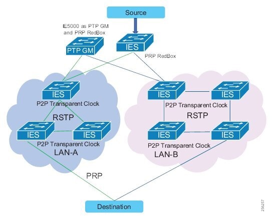
Recommendations for this topology:
■![]() It is recommended to use fiber links since they provide faster convergence than copper links.
It is recommended to use fiber links since they provide faster convergence than copper links.
■![]() Link bandwidth impacts the latency and the number of nodes that could be part of the HSR and PRP networks.
Link bandwidth impacts the latency and the number of nodes that could be part of the HSR and PRP networks.
■![]() GOOSE and Sample Values were classified and transmitted in priority queue on the egress interface.
GOOSE and Sample Values were classified and transmitted in priority queue on the egress interface.
■![]() Configure unique VLANs for each IED to avoid multicast flooding.
Configure unique VLANs for each IED to avoid multicast flooding.
■![]() Enable storm control on the access/IED facing interfaces.
Enable storm control on the access/IED facing interfaces.
| | | | | |
| | | |||
| | | | | |
| | | | | |
| | | | | |
| | | | | |
| | | | | |
High Availability Seamless Redundancy (HSR)
HSR is defined in International Standard IEC 62439-3-2016 clause 5. HSR has been seen primarily in utility IEC 61850 substation architectures, however, its lossless redundancy features make it a viable option for other plant-based environments where IACS applications require better ring convergence than REP. HSR is similar to PRP but is designed to work in a ring topology. Instead of two parallel independent networks of any topology (LAN-A and LAN-B), HSR defines a ring with traffic in opposite directions. Port-A sends traffic counterclockwise in the ring and Port-B sends traffic clockwise in the ring. The duplicated packet mechanism provides lossless redundancy under a single failure within the ring.
The HSR packet format is also different from PRP. To allow the switch to determine and discard duplicate packets, additional protocol-specific information is sent with the data frame. For PRP this is part of the RCT, whereas for HSR this is sent as part of the header. Both the RCT and HSR header contain a sequence number, which is the primary data used to determine if the received frame is the first instance or a duplicate instance.
The non-switching nodes with two interfaces attached to the HSR ring are referred to as Doubly Attached Nodes implementing HSR (DANHs). Similar to PRP, SANs are attached to the HSR ring through a RedBox The RedBox acts as a DANH for all traffic for which it is the source or the destination. The switch implements RedBox functionality using Gigabit Ethernet port connections to the HSR ring.
Figure 37 shows an example of an HSR ring as described in IEC 62439-3. In this example, the RedBoxes are Cisco IE 4000 switches. The Cisco IE 4000 or Cisco IE 4010 and Cisco IE 5000 switches are the only switches that will support an HSR deployment.
Figure 37 HSR Overview and Packet Flows
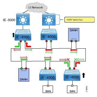
Devices that do not support HSR out of the box (for example, laptops and printers) cannot be attached to the HSR ring directly because all HSR capable devices must be able to process the HSR header on packets received from the ring and add the HSR header to all packets sent into the ring. These nodes are attached to the HSR ring through a RedBox. As shown in Figure 37, the RedBox has two ports on the DANH side. Non-HSR SAN devices are attached to the upstream switch ports. The RedBox generates the supervision frames on behalf of these devices so that they are seen as DANH devices on the ring. Because the RedBox emulates these as DANH, they are called Virtual Doubly Attached Nodes (VDAN).
HSR Loop Avoidance
To avoid loops and use network bandwidth effectively, the RedBox does not transmit frames that are already transmitted in the same direction. When a node injects a packet into the ring, the packet is handled as follows to avoid loops:
■![]() Unicast packet with destination inside the ring—When the unicast packet reaches the destination node, the packet is consumed by the respective node and is not forwarded.
Unicast packet with destination inside the ring—When the unicast packet reaches the destination node, the packet is consumed by the respective node and is not forwarded.
■![]() Unicast packet with destination not inside the ring—Because this packet does not have a destination node in the ring, it is forwarded by every node in the ring until it reaches the originating node. Because every node has a record of the packet it sent, along with the direction in which it was sent, the originating node detects that packet has completed the loop and drops the packet. This is illustrated in Figure 37 at the originating node.
Unicast packet with destination not inside the ring—Because this packet does not have a destination node in the ring, it is forwarded by every node in the ring until it reaches the originating node. Because every node has a record of the packet it sent, along with the direction in which it was sent, the originating node detects that packet has completed the loop and drops the packet. This is illustrated in Figure 37 at the originating node.
■![]() Multicast packet—A multicast packet is forwarded by each node because there can be more than one consumer of this packet. For this reason, a multicast packet always reaches the originating node. However, every node will check whether it has already forwarded the received packet through its outgoing interface. Once the packet reaches the originating node, the originating node determines that it already forwarded this packet and drops the packet instead of forwarding it again.
Multicast packet—A multicast packet is forwarded by each node because there can be more than one consumer of this packet. For this reason, a multicast packet always reaches the originating node. However, every node will check whether it has already forwarded the received packet through its outgoing interface. Once the packet reaches the originating node, the originating node determines that it already forwarded this packet and drops the packet instead of forwarding it again.
HSR RedBox Modes of Operation
An HSR RedBox can operate in one of the following modes that define how HSR handles packets in different scenarios:
■![]() HSR-SAN—This is the most basic mode. In this mode, the RedBox connects SAN devices to an HSR Ring. No other PRP or HSR network is involved in this configuration. In this mode, the traffic on the upstream switch port does not have HSR/PRP tags and the RedBox represents the SAN device as a VDAN in the ring.
HSR-SAN—This is the most basic mode. In this mode, the RedBox connects SAN devices to an HSR Ring. No other PRP or HSR network is involved in this configuration. In this mode, the traffic on the upstream switch port does not have HSR/PRP tags and the RedBox represents the SAN device as a VDAN in the ring.
■![]() HSR-PRP—This configuration is used to bridge HSR and PRP networks. The RedBox extracts the data from the PRP frame and generates the HSR frame using this data and it performs the reverse operation for packets in the opposite direction. This is more prevalent in utility substations deploying IEC 61850, but again could be an option if lossless redundancy for plants is required where two rings are being bridged.
HSR-PRP—This configuration is used to bridge HSR and PRP networks. The RedBox extracts the data from the PRP frame and generates the HSR frame using this data and it performs the reverse operation for packets in the opposite direction. This is more prevalent in utility substations deploying IEC 61850, but again could be an option if lossless redundancy for plants is required where two rings are being bridged.
Figure 38 HSR and HSR-PRP Overview
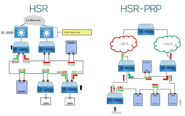
For more information on HSR and its features see:
https://www.cisco.com/c/en/us/td/docs/switches/connectedgrid/cg-switch-sw-master/software/configuration/guide/hsr/b_hsr_ie4k.html#id_54474
HSR Summary
■![]() Lossless redundancy over a ring topology
Lossless redundancy over a ring topology
■![]() All nodes in the ring must have special hardware to support HSR and all nodes in the ring must support HSR.
All nodes in the ring must have special hardware to support HSR and all nodes in the ring must support HSR.
■![]() Useful for networks that require faster convergence than REP as it provides lossless redundancy
Useful for networks that require faster convergence than REP as it provides lossless redundancy
■![]() IEC 62439-3 Clause 5 standard
IEC 62439-3 Clause 5 standard
■![]() Supported on Cisco IE 4000, Cisco IE 4010, and Cisco IE 5000 only
Supported on Cisco IE 4000, Cisco IE 4010, and Cisco IE 5000 only
■![]() Bandwidth available in ring is reduced by up to half due to duplicate packets
Bandwidth available in ring is reduced by up to half due to duplicate packets
■![]() In a typical implementation, the receiving node removes both packets from the HSR Ring.
In a typical implementation, the receiving node removes both packets from the HSR Ring.
HSR Topologies Design and Recommendations
Cisco Catalyst 9300/Cisco Catalyst 3850 StackWise REP and HSR with Cisco IE 4000 Switches
This topology uses StackWise for distribution redundancy. It uses REP for connectivity between the access ring and the distribution as shown in Figure 39. HSR is implemented in the access ring topology. REP is used between the links which directly connect the IE access and Cisco Catalyst 9300 distribution switches. REP edge ports are configured on the access switch uplinks as shown in Figure 39. A disruption in this topology has zero downtime for traffic in the ring. A failure in the REP ring will have an impact on Layer 3 traffic according to REP convergence times. This topology without REP will result in network loops.
Figure 39 Cisco Catalyst 9300/Cisco Catalyst 3850 StackWise REP and HSR with Cisco IE 4000 Switches
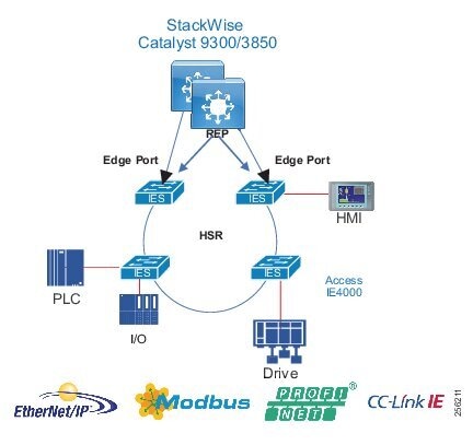
Table 24 summarizes convergence results during validation.
| | | | |
| | | ||
| | | | |
| | | | |
| | | | |
| | | | |
| | | | |
| | | | |
HSR-HSR
HSR rings can also be implemented in such a way that key switches are participating in two HSR rings, using four interfaces to connect the respective rings, which is known as HSR-HSR or Quadbox. When the HSR-HSR mode is licensed and enabled, the switch shuts all non-HSR ports to avoid traffic interference. Connectivity to the HSR-HSR switch can be done through the HSR-HSR ports or the out-of-band console interface.
Figure 40 HSR-HSR Ring with Cisco Catalyst 9300 in Distribution
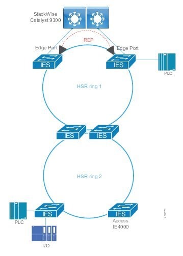
| | | | |
| | | ||
| | | | |
| | | | |
| | | | |
| | | | |
| | | | |
| | | | |
Figure 41 HSR-HSR Ring with Cisco IE 5000 in Distribution
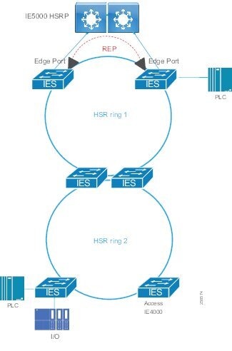
| | | | |
| | | ||
| | | | |
| | | | |
| | | | |
| | | | |
| | | | |
| | | | |
Result considerations:
■![]() The validation of HSR-HSR was done with two rings containing Cisco IE 4000 switches connected with copper Ethernet. An open REP segment connected one HSR ring to the distribution switches using copper Ethernet.
The validation of HSR-HSR was done with two rings containing Cisco IE 4000 switches connected with copper Ethernet. An open REP segment connected one HSR ring to the distribution switches using copper Ethernet.
■![]() Convergence was validated for Layer 2 traffic within a VLAN and Layer 3 traffic between VLANs in the same ring.
Convergence was validated for Layer 2 traffic within a VLAN and Layer 3 traffic between VLANs in the same ring.
■![]() Link disruptions refer to a single link failure in the ring. Link failures were conducted at varying points across both HSR rings. Switch failures refer to power interruption of a single switch at a time; distribution members and IE switches were reloaded during testing.
Link disruptions refer to a single link failure in the ring. Link failures were conducted at varying points across both HSR rings. Switch failures refer to power interruption of a single switch at a time; distribution members and IE switches were reloaded during testing.
■![]() Link or switch failures outside of the HSR rings, in other words the links to the distribution or the distribution switches themselves, caused Layer 3 unicast packet loss for the switches in the HSR rings. The convergence time for these failures aligns with expectations for REP convergence over copper links.
Link or switch failures outside of the HSR rings, in other words the links to the distribution or the distribution switches themselves, caused Layer 3 unicast packet loss for the switches in the HSR rings. The convergence time for these failures aligns with expectations for REP convergence over copper links.
■![]() Simulated traffic and real IACS devices were used during validation.
Simulated traffic and real IACS devices were used during validation.
■![]() The scenario was run with 250 MAC addresses, 200 multicast groups, and inter- and intra-VLAN traffic.
The scenario was run with 250 MAC addresses, 200 multicast groups, and inter- and intra-VLAN traffic.
HSR-PRP Redbox for Multilevel Rings
HSR-PRP, also known as Dual Redbox, is used to connect PRP and HSR networks together. It is commonly deployed in utility substations, hence the testing results show GOOSE and Sampled Values but are applicable to other IP protocols. The following topology shows an HSR ring connected to a PRP network through two Red Boxes, one for each LAN. In this example, the IP frame originates in the PRP network and GOOSE and Sample Value frames originate and end in the HSR ring. A disruption in this topology has zero downtime for corresponding traffic and ensures that the latency for different traffic streams meet the expected requirements.
Figure 42 HSR-PRP Redbox for Multilevel Rings
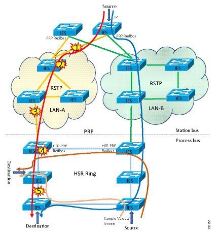
Recommendations for this topology:
■![]() Link bandwidth impacts the latency and the number of nodes that could be part of the HSR and PRP networks.
Link bandwidth impacts the latency and the number of nodes that could be part of the HSR and PRP networks.
■![]() HSR-PRP feature is supported only on Cisco IE 4000.
HSR-PRP feature is supported only on Cisco IE 4000.
■![]() GOOSE and Sample Values were classified and transmitted in priority queue on the egress interface.
GOOSE and Sample Values were classified and transmitted in priority queue on the egress interface.
■![]() Configure unique VLANs for each IED to avoid multicast flooding.
Configure unique VLANs for each IED to avoid multicast flooding.
■![]() Enable storm control on the access facing interfaces.
Enable storm control on the access facing interfaces.
| | | | | |
| | | |||
| | | | | |
| | | | | |
| | | | | |
| | | | | |
| | | | | |
| | | | | |
Result considerations:
■![]() Convergence and Latency was validated for Layer 2 GOOSE, Sample Values, and IP traffic with unique VLANs for each type in the same ring.
Convergence and Latency was validated for Layer 2 GOOSE, Sample Values, and IP traffic with unique VLANs for each type in the same ring.
■![]() Link disruptions refer to a link failure in the active forwarding path. Switch failures refer to primary switch failure in the active forwarding path.
Link disruptions refer to a link failure in the active forwarding path. Switch failures refer to primary switch failure in the active forwarding path.
■![]() The HSR ring had eight Cisco IE 4000 switches.
The HSR ring had eight Cisco IE 4000 switches.
■![]() PRP network had three and four Cisco IE 4010 switches as part of two different PRP LANs running RSTP for loop avoidance.
PRP network had three and four Cisco IE 4010 switches as part of two different PRP LANs running RSTP for loop avoidance.
■![]() Cisco IE 4010 and Cisco IE 5000 switches were configured as PRP Redundant nodes.
Cisco IE 4010 and Cisco IE 5000 switches were configured as PRP Redundant nodes.
■![]() The tests were carried out using GigabitEthernet links in the network.
The tests were carried out using GigabitEthernet links in the network.
Media Redundancy Protocol (MRP)—PROFINET Deployments
The media redundancy protocol (MRP) is a data network protocol standardized by the International Electrotechnical Commission (IEC) as IEC 62439-2. The MRP allows rings of Ethernet switches to overcome a single failure with recovery time much faster than achievable with traditional STP.
Roles—Cisco Industrial Ethernet switches support the following two roles:
■![]() Media Redundancy Manager (MRM)
Media Redundancy Manager (MRM)
■![]() Media Redundancy Client (MRC)
Media Redundancy Client (MRC)
In a ring topology, only one switch or industrial automation System device can act as an MRM; all other devices will act as an MRC. The purpose of an MRM is to keep the ring loop free and provide redundancy when failure happens. The MRM does this by sending a control packet from one ring port and receiving them on its other ring port in both directions. If it receives the control packets then the ring is in an error-free state.
There are three port states used within MRP:
■![]() Disconnected/Disabled—In this state, switch port will drop all received packets.
Disconnected/Disabled—In this state, switch port will drop all received packets.
■![]() Blocked—In this state, all received frames are dropped except control packets.
Blocked—In this state, all received frames are dropped except control packets.
■![]() Forwarding—Normal working state that forward all received packets on the port.
Forwarding—Normal working state that forward all received packets on the port.
During normal operation, the network operates in the closed state. In this state, one MRM one ring port remains in a blocked port status and the other port is in the forwarding status. All MRCs will be in forwarding status as well. Loops are avoided because of the blocked port on the MRM.
Figure 43 MRP Normal Mode of Operations
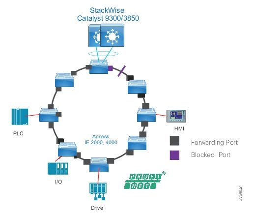
When a network link or device fails, the ring transitions to the open status. When there is a failure as detailed in Figure 44, the MRM will not receive the control frame and assume a failure in the ring. The MRM will move its previously blocked port to the forwarding state so that both ports are forwarding.
Figure 44 MRP Failure
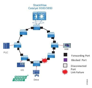
MRP Summary
Advantages include:
■![]() Fast convergence—MRP can provide convergence times of 200ms.
Fast convergence—MRP can provide convergence times of 200ms.
■![]() Link integrity—MRP does not use an end-to-end polling function between edge ports to verify link Integrity. It implements local link failure detection.
Link integrity—MRP does not use an end-to-end polling function between edge ports to verify link Integrity. It implements local link failure detection.
■![]() Co-existence with Resilient Ethernet Protocol (REP)—MRP does not interact with REP but can coexist on the same switch. This allows the network architect to create advance interoperable rings.
Co-existence with Resilient Ethernet Protocol (REP)—MRP does not interact with REP but can coexist on the same switch. This allows the network architect to create advance interoperable rings.
■![]() Device level ring support—Because MRP is a inbuilt resiliency protocol for PROFINET Cisco
Device level ring support—Because MRP is a inbuilt resiliency protocol for PROFINET Cisco
■![]() Industrial Ethernet switch can form a ring with IACS devices, such as, PLC, Remote I/O.
Industrial Ethernet switch can form a ring with IACS devices, such as, PLC, Remote I/O.
Disadvantages include:
■![]() License requirement for Manager node.
License requirement for Manager node.
■![]() Does not support multi-ring topologies.
Does not support multi-ring topologies.
■![]() No hardware level redundancy for Manager (MRM).
No hardware level redundancy for Manager (MRM).
■![]() Slower convergence than Cisco REP.
Slower convergence than Cisco REP.
| | | | | ||
| | | | | ||
| | | | | | |
| | | | | | |
| | | | | | |
| | | | | | |
| | | | | | |
| | | | | | |
| | | | | ||
| | | | | ||
| | | | | | |
| | | | | | |
| | | | | | |
| | | | | | |
| | | | | | |
| | | | | | |
Result considerations:
■![]() The MRP ring contained IE switches of the following types:
The MRP ring contained IE switches of the following types:
–![]() Cisco IE 2000
Cisco IE 2000
–![]() Cisco IE 3400
Cisco IE 3400
–![]() Cisco IE 4000
Cisco IE 4000
■![]() The switch roles were configured through Siemens TIA portal.
The switch roles were configured through Siemens TIA portal.
■![]() Convergence was validated for Layer 2 traffic within a VLAN and Layer 3 traffic between VLANs in the same ring.
Convergence was validated for Layer 2 traffic within a VLAN and Layer 3 traffic between VLANs in the same ring.
■![]() Link disruptions refer to a single link failure in the ring. Link failures were conducted at varying points in the ring. Switch failures refer to power interruption of a single switch at a time.
Link disruptions refer to a single link failure in the ring. Link failures were conducted at varying points in the ring. Switch failures refer to power interruption of a single switch at a time.
■![]() Simulated traffic and real IACS devices were used during validation.
Simulated traffic and real IACS devices were used during validation.
■![]() The scenario was run with 250 MAC addresses, 200 multicast groups, and inter- and intra-VLAN traffic.
The scenario was run with 250 MAC addresses, 200 multicast groups, and inter- and intra-VLAN traffic.
Resiliency Summary and Comparison
Table 30 provides high-level guidance on resiliency protocols based on performance and interoperability. Note the maximum number of nodes is generally a recommendation, rather than an absolute limit.
| Protocol | Topology | Number of Nodes | Typical Convergence | Remark |
|---|---|---|---|---|
| RSTP/MSTP | Any | Max hops 255 | 50 ms - 6 seconds | Provides widest interoperability but poorest convergence and troubleshooting |
| MRP | Ring | 50 | 200 - 500 ms | Siemens is big proponent. Interoperable with switches that support Standard IEC 62439-2. Common in PROFINET environment. |
| REP | Ring | 50 | 50 - 250 ms | Cisco proprietary. Very easy setup and troubleshooting. |
| PRP | Any | Unlimited | 0 ms | Duplicate LANs required.(expensive) Standard IEC 62439-3 Clause 4 |
| HSR | Ring | 50 | 0 ms | Requires all nodes in Ring support HSR. Standard IEC 62439-3 Clause 5 |
Note: RSTP and MSTP were not verified in this CVD and are only added for informational purposes.
Platform specifics and distribution switch redundancy mechanisms do factor into the equation and should also be considered. These can be found in the relevant sections in this DIG under each of the resiliency protocols for the Industrial Automation DIG validation. The number of nodes validated are also detailed.
Cell/Area Zone Management
Ethernet networks are an integral part of modern automation and control environments and operations personnel are growing increasingly dependent on network monitoring to reduce unplanned downtime. Therefore, OT control engineers are taking on more of a role for basic network management functions. The control engineers require visibility and access to the network when issues arise so network management must address the following key considerations:
■![]() The management network should have a separate out-of-band infrastructure, as mentioned in Network Hardening—A Component of System Integrity. At a minimum it should have its own logical network so as to provide network connectivity to the Cell/Area Zone networking devices even when the in-band data plane network is impacted. The out-of-band network segments hosts console servers, network management stations, AAA servers, analysis and correlation tools, FTP, syslog servers, network compliance management, and any other management and control services. An out-of-band management network should be deployed using the following best practices:
The management network should have a separate out-of-band infrastructure, as mentioned in Network Hardening—A Component of System Integrity. At a minimum it should have its own logical network so as to provide network connectivity to the Cell/Area Zone networking devices even when the in-band data plane network is impacted. The out-of-band network segments hosts console servers, network management stations, AAA servers, analysis and correlation tools, FTP, syslog servers, network compliance management, and any other management and control services. An out-of-band management network should be deployed using the following best practices:
–![]() Provide network isolation
Provide network isolation
–![]() Enforce access control
Enforce access control
–![]() Prevent data traffic from transiting the management network
Prevent data traffic from transiting the management network
–![]() Enforce secure use of network management traffic (SSH, Simple Network Management Protocol Version 3 [SNMPv3])
Enforce secure use of network management traffic (SSH, Simple Network Management Protocol Version 3 [SNMPv3])
–![]() Provide visibility of events, faults, and performance of the network to the operators in the control center using syslog and SNMP
Provide visibility of events, faults, and performance of the network to the operators in the control center using syslog and SNMP
–![]() If an out-of-band network is not viable, then a dedicated VLAN should be used for the management network.
If an out-of-band network is not viable, then a dedicated VLAN should be used for the management network.
■![]() Within the Cell/Area Zone, the tools provided to help assist with the management of the network must provide an OT view that is familiar to a control engineer. It should look and feel like a component or extension of the IACS system rather than an IT network management tool.
Within the Cell/Area Zone, the tools provided to help assist with the management of the network must provide an OT view that is familiar to a control engineer. It should look and feel like a component or extension of the IACS system rather than an IT network management tool.
■![]() The network should be easy to deploy, configure, and monitor. Network components should be easy to replace or install for the OT experienced controls engineer.
The network should be easy to deploy, configure, and monitor. Network components should be easy to replace or install for the OT experienced controls engineer.
Cisco has tools to address the requirements of the OT controls engineer in this space: Cisco IND and the IoT Device Manager (IoT-DM). Figure 45 highlights the network management support model for the Industrial Automation architecture. IoT-DM and IND are highlighted as the tools to support the Cell/Area Zone. Cisco DNA Center (DNA-C) is positioned as the tool to assist with network management at the operations layer where an IT-based team would provide network management functions in support of the industrial plant.
Figure 45 Network Management Support Model

Note: Cisco Prime and DNAC were not tested as part of this CVD.
Cisco Industrial Network Director
The Cisco IND provides operations-centric network management for industrial Ethernet networks. The system supports industrial automation protocols such as CIP, PROFINET, OPC-UA, Modbus, BACnet, and so on to discover automation devices such as PLC, I/O, HMI, and drives and delivers an integrated topology map of automation and networking assets; this provides a common framework for operations and plant IT personnel to manage and maintain the industrial network.
The system uses the full capabilities of the Cisco IE product portfolio to make the network accessible to non-IT operations personnel. The simple user interface streamlines network monitoring and delivers rapid troubleshooting of common network problems found in industrial environments. For more information see:
https://www.cisco.com/c/dam/en/us/products/collateral/cloud-systems-management/industrial-network-director/datasheet-c78-737848.pdf
At a high level the following features address the management requirements detailed earlier for the Cell/Area Zone:
■![]() Plug-and-play server for switch commissioning-The Cisco IND provides a plug-and-play server for the provisioning and replacement of industrial Ethernet devices. Pre-provisioned configuration and software for automated network commissioning help to ensure a consistent network design and security policy. A controls engineer now has an easy way to replace faulty network equipment such as the network switch. The engineer can swap the hardware when the switch fails and replace back into the network with the automated configuration and software image replacement using the IND plug-and-play feature.
Plug-and-play server for switch commissioning-The Cisco IND provides a plug-and-play server for the provisioning and replacement of industrial Ethernet devices. Pre-provisioned configuration and software for automated network commissioning help to ensure a consistent network design and security policy. A controls engineer now has an easy way to replace faulty network equipment such as the network switch. The engineer can swap the hardware when the switch fails and replace back into the network with the automated configuration and software image replacement using the IND plug-and-play feature.
■![]() Automated discovery of industrial and network assets-Cisco IND not only discovers the networking topology but it can discover automation devices with Common Industrial Protocol (CIP), PROFINET, Modbus, OPC-UA, BACnet, Siemens S7, and other industrial communication protocols. The user interface can provide visibility of connectivity between automation and networking assets on a dynamic topology map.
Automated discovery of industrial and network assets-Cisco IND not only discovers the networking topology but it can discover automation devices with Common Industrial Protocol (CIP), PROFINET, Modbus, OPC-UA, BACnet, Siemens S7, and other industrial communication protocols. The user interface can provide visibility of connectivity between automation and networking assets on a dynamic topology map.
■![]() Network management-Building on top of the plug-and-play support of the IE switches, Cisco IND can provide continuous monitoring of switch health and traffic statistics and switch configuration backup. GUI-driven actions let non-IT operations personnel securely add automation devices to existing network infrastructure. Cisco IND can provide detailed audit trails to track and adds moves or changes in the network.
Network management-Building on top of the plug-and-play support of the IE switches, Cisco IND can provide continuous monitoring of switch health and traffic statistics and switch configuration backup. GUI-driven actions let non-IT operations personnel securely add automation devices to existing network infrastructure. Cisco IND can provide detailed audit trails to track and adds moves or changes in the network.
■![]() Ease of troubleshooting- When there is unplanned downtime or networking issues the management platform needs to pinpoint issues and recover quickly. Cisco IND can visualize and provide alerts to networking events with contextualized industrial asset visibility.
Ease of troubleshooting- When there is unplanned downtime or networking issues the management platform needs to pinpoint issues and recover quickly. Cisco IND can visualize and provide alerts to networking events with contextualized industrial asset visibility.
■![]() Role-based access control (RBAC)-Cisco IND is ideal for environments where different types of users need different levels of information and access. The ability to create multiple users and lock down their access to specific areas within the Cisco IND user interface ensures that only authorized personnel are able to perform more sensitive operations.
Role-based access control (RBAC)-Cisco IND is ideal for environments where different types of users need different levels of information and access. The ability to create multiple users and lock down their access to specific areas within the Cisco IND user interface ensures that only authorized personnel are able to perform more sensitive operations.
■![]() Rich application programming interfaces (APIs) for rapid integration with industrial applications-Cisco IND includes a comprehensive RESTful API allowing it to easily integrate with existing industrial asset management tools, automation applications, and control systems. An intuitive API tool is included with Cisco IND to help system integrators and developers rapidly learn and adopt the API.
Rich application programming interfaces (APIs) for rapid integration with industrial applications-Cisco IND includes a comprehensive RESTful API allowing it to easily integrate with existing industrial asset management tools, automation applications, and control systems. An intuitive API tool is included with Cisco IND to help system integrators and developers rapidly learn and adopt the API.
Cisco IND Deployment Options and Considerations
Cisco IND can be installed on a server in the industrial zone with tightly restricted access to other areas of the network. It is recommended to use only secure protocols (such as HTTPS and SSH) when possible to protect critical data. If required, Cisco IND is lightweight enough to be installed on a ruggedized laptop that resides within a zone on a plant floor, as long as it meets the system requirements. Figure 46 highlights the position in the architecture for Cisco IND. The example shows a server in the Industrial zone and a secure, ruggedized laptop in the Cell/Area Zone (the laptop connectivity is not shown).
Figure 46 Cisco IND Deployment and Considerations
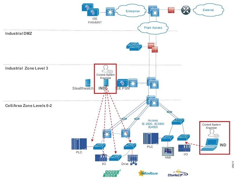
■![]() The Cisco IND application requires Layer 3 connectivity to all of the network assets and automation clients that it is tasked with discovering and monitoring. This means that all devices that need to be discovered and monitored should have an IP address assigned that is routable and able to reach the Cisco IND server.
The Cisco IND application requires Layer 3 connectivity to all of the network assets and automation clients that it is tasked with discovering and monitoring. This means that all devices that need to be discovered and monitored should have an IP address assigned that is routable and able to reach the Cisco IND server.
■![]() If there is a firewall located between the Windows server hosting Cisco IND and the monitored devices, the firewall must be configured to allow the following protocols and ports through both inbound and outbound: TCP ports 5432, 8088, 8443, 443, 80, 21, and 50000-50050.
If there is a firewall located between the Windows server hosting Cisco IND and the monitored devices, the firewall must be configured to allow the following protocols and ports through both inbound and outbound: TCP ports 5432, 8088, 8443, 443, 80, 21, and 50000-50050.
■![]() In order to use the Cisco Active Advisor integration, the client computer which is accessing the Cisco IND web interface also needs to have Internet access to be able to upload network inventory data.
In order to use the Cisco Active Advisor integration, the client computer which is accessing the Cisco IND web interface also needs to have Internet access to be able to upload network inventory data.
Note: Depending on technical and business requirements, direct access to the Internet for Cisco Smart Licensing may not be available. In this situation, Cisco Software Manager Satellite can be positioned in the IDMZ between the IND server and the Cisco cloud to facilitate license management on premise.
Cisco IND Supported Platforms
■![]() Cisco IE 1000
Cisco IE 1000
■![]() Cisco IE 2000
Cisco IE 2000
■![]() Cisco IE 3200
Cisco IE 3200
■![]() Cisco IE 3300
Cisco IE 3300
■![]() Cisco IE 3400
Cisco IE 3400
■![]() Cisco IE 4000
Cisco IE 4000
■![]() Cisco IE 4010
Cisco IE 4010
■![]() Cisco IE 5000
Cisco IE 5000
Cisco IND Supported Industrial Protocols
■![]() CIP
CIP
■![]() PROFINET I&M
PROFINET I&M
■![]() Siemens S7
Siemens S7
■![]() Modbus/TCP
Modbus/TCP
■![]() BACnet/IP
BACnet/IP
■![]() OPC-UA
OPC-UA
Cisco IND System Requirements
Figure 47 Cisco IND System Requirements
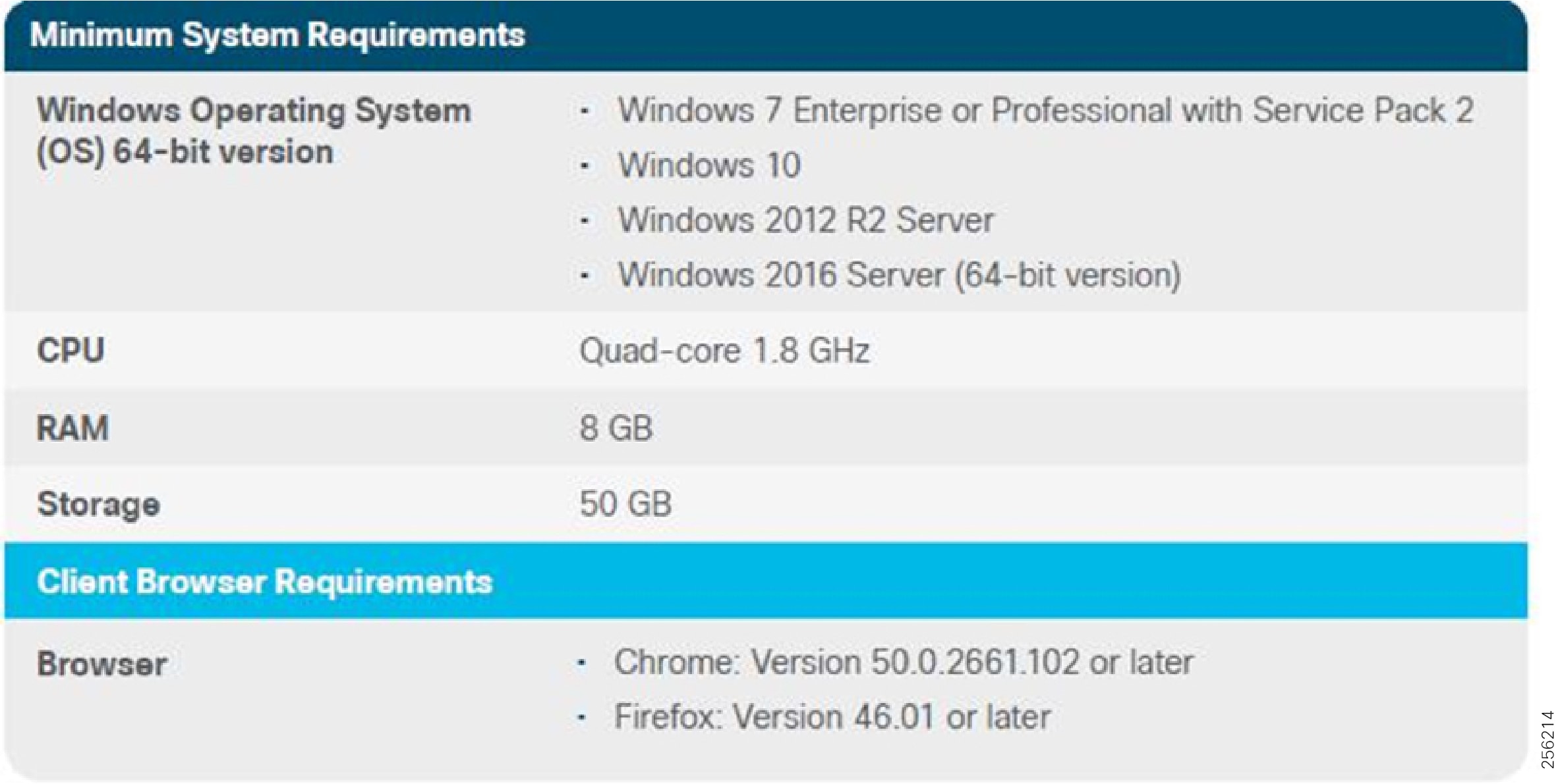
Cisco IoT Device Manager
The Device Manager is in the switch memory to manage individual and standalone switches. This web interface provides a user-friendly web device manager for easy out-of-the-box configuration and simplified operational manageability. You can access Device Manager from anywhere in your network through a web browser. The Device manager can be used to supplement the features and functions of the Cisco IND. The device manager eliminates the need for complex terminal emulation programs to configure the switch through a CLI. Modifications to switch configurations can be replicated to Cisco IND.
Cisco Cyber Vision Overview
IACS are deployed for automation in production lines, in water, gas and electricity distribution networks, running power plants and critical infrastructure, transportation networks, and more. These systems are increasingly connected to corporate IT networks and companies are now also deploying Industrial Internet of Things (IIoT) technologies to drive further digitization. This deeper integration between IT, cloud, and industrial networks is creating many security issues that are obstacles to industry digitization efforts.
Protecting industrial operations is a very specific challenge. Industrial processes should not be stopped and disruption can lead to dramatic human or environmental hazards. Attacks are particularly difficult to detect as they are often custom-made, look like legitimate instructions to assets, and have effects after a long period of maturing. Industrial automation technologies can be quite old, proprietary, and not designed with security in mind.
Cisco Cyber Vision is a cybersecurity solution specifically designed for organizations in manufacturing, oil and gas, power and water distribution, and public transportation to ensure continuity, resilience, and safety of their industrial operations. It provides asset owners with full visibility into their IACS networks so they can ensure operational and process integrity, drive regulatory compliance, and enable easy deployment within the industrial network. Cisco Cyber Vision leverages Cisco industrial network equipment to monitor industrial operations and feeds Cisco IT security platforms with OT context to build a unified IT/OT cybersecurity architecture.
Cisco Cyber Vision provides three key value propositions:
■![]() Visibility embedded in your Industrial Network—Know what to protect. Cisco Cyber Vision is embedded in your Cisco industrial network equipment so you can see everything that connects to it, enabling customers to segment their network and deploy IoT security at scale.
Visibility embedded in your Industrial Network—Know what to protect. Cisco Cyber Vision is embedded in your Cisco industrial network equipment so you can see everything that connects to it, enabling customers to segment their network and deploy IoT security at scale.
■![]() Security insights for IACS and OT—Continuously monitor IACS cybersecurity integrity to help maintain system integrity and production continuity. Cisco Cyber Vision understands proprietary industrial protocols and keeps track of process data, asset modifications, and variable changes.
Security insights for IACS and OT—Continuously monitor IACS cybersecurity integrity to help maintain system integrity and production continuity. Cisco Cyber Vision understands proprietary industrial protocols and keeps track of process data, asset modifications, and variable changes.
■![]() 360° threat detection—Detect threats before it is too late. Cisco Cyber Vision leverages Cisco threat intelligence and advanced behavioral analytics to identify known and emerging threats as well as process anomalies and unknown attacks. Fully integrated with Cisco security portfolio, it extends the IT SOC to the OT domain.
360° threat detection—Detect threats before it is too late. Cisco Cyber Vision leverages Cisco threat intelligence and advanced behavioral analytics to identify known and emerging threats as well as process anomalies and unknown attacks. Fully integrated with Cisco security portfolio, it extends the IT SOC to the OT domain.
Key Features and Benefits
Security Built Into your Industrial Network
Deploying OT cybersecurity can quickly become very complex, especially if the industrial network is dispersed across an entire country or many remote industrial sites. For your OT cybersecurity project to be successful, you must be able to scale it easily and at a reasonable cost across your entire organization.
Cisco Cyber Vision leverages a unique edge computing architecture that enables security monitoring components to run within Cisco industrial network equipment (IoT switches, routers, access points, industrial compute, and so on). There is no need to source dedicated appliances and think about how to install them or build an out-of-band network to send industrial network flows to a central security platform. Cisco Cyber Vision enables the industrial network to collect the information required to provide comprehensive visibility, analytics, and threat detection. Network managers will appreciate the unique simplicity and the lower costs of the Cisco Cyber Vision architecture when deploying OT security at scale.
Visibility
Securing your OT infrastructure starts with having a precise view of your asset inventory, communication patterns, and network topologies. Cisco Cyber Vision gives OT teams and network managers full visibility of their assets and application flows so they can implement security best practices, drive network segmentation projects, and improve operational resilience.
Cisco Cyber Vision automatically uncovers the smallest details of the production infrastructure: vendor references, firmware and hardware versions, serial numbers, PLC rack slot configuration, and so on. It identifies asset relationships, communication patterns, changes to variables, and more. This wealth of information is shown in various types of maps, tables, and reports that maintain a complete inventory of industrial assets, their relationships, their vulnerabilities, and the programs they run.
Operational Insights
Cisco Cyber Vision gives OT engineers real-time insight into the actual industrial process status, such as unexpected variable changes or controller modifications. They can take action to maintain system integrity and production continuity. Cyber experts can easily dive into all this data to analyze attacks and find the source. CISOs have all the information to document their incident reports.
Cisco Cyber Vision "understands" the proprietary OT protocols used by automation equipment, so it can track process anomalies, errors, misconfigurations, and unauthorized industrial events. It also records everything and so serves as a kind of "flight recorder" of the industrial infrastructure.
Threat Detection
As industrial networks are ever more connected to IT networks, they must be protected from the usual IT threats such as malware or intrusion. And as attacks on industrial networks generally look like legitimate instructions to assets, you also need to detect those unwanted process modifications. To secure an industrial network, you need a variety of threat detection mechanisms.
Cisco Cyber Vision combines protocol analysis, intrusion detection, and behavioral analysis to detect any attack tactic. Future versions of this guide will provide additional details.
Use Cases
Security Assessments
Securing your OT infrastructure starts with having a precise view of your asset inventory, communication patterns, and network topologies. An industrial cybersecurity project generally starts with a security assessment to understand the situation and define what needs to be done.
Cisco Cyber Vision automatically builds an accurate list of all your industrial assets down to the component level. It identifies communication flows between assets and to and from the IT domain and builds your network map. It lists devices with vulnerabilities, including severity levels, detailed descriptions, and solution guidelines. It also spots devices with weak credentials such as default passwords.
Network Segmentation
Industrial security best practices suggest migrating networks towards architectures compliant with IEC62443 zones and conduits. In other words, you want to place assets that do not need to talk to each other into network segments and manage access between those segments or zones to avoid an attack spreading to your entire industrial infrastructure.
Cisco Cyber Vision gives you an accurate view of your assets, network connections, and remote accesses so you can build a network that is secure by design and that can be effectively monitored. It lets you group assets and define their "industrial impact" so you can prioritize and score events according to your own industrial safety targets. It summarizes all flows between zones so you can focus on monitoring the relevant traffic.
Extending Cybersecurity to the OT Domain
Protecting your industrial network against cyber-attacks is critical to ensure production integrity, continuity, and safety. As the industrial domain is exposed to both traditional IT threats and custom-made attacks aiming at modifying the industrial process, you need holistic threat detection techniques.
Cisco Cyber Vision combines protocol analysis, intrusion detection, behavioral analysis, and OT threat intelligence to detect asset vulnerabilities, known and emerging attacks, as well as malicious behaviors that could be warning signs of unknown attacks. It continuously monitors application flows so that threats are detected in real time. Alerts are automatically generated and can be used to trigger remediation from existing IT security platforms such as firewalls.
Enabling a Converged IT and OT SOC
Leverage the time and money you have invested in your IT cybersecurity environment to monitor your OT network and manage threats to your industrial network. Give OT context to your IT SOC so you can build and enforce security policies that are compliant with the specific constrains of your industrial infrastructure.
Cisco Cyber Vision is part of the Cisco industry-leading security portfolio. It brings detailed information on OT assets and industrial threat detection to Firepower firewalls and Stealthwatch traffic analyzer to enable unique security features. Cisco Cyber Vision also integrates with leading SIEM platforms so you can collect all OT events in your IT SOC and build a unified IT/OT threat management.
Driving Governance and Compliance
Whether you are responsible for a critical site or a small factory, you need detailed information in your OT security posture to comply with the latest regulatory requirements (EU NIS, NERC CIP, FDA, and so on) and work with both IT and OT teams to drive actions.
Cisco Cyber Vision logs all events from your IACS and gives you access the entire history so you can run efficient audits and have detailed information on assets and events to build incident reports. Cisco Cyber Vision offers a friendly user interface that lets everyone share a common understanding of what is occurring so OT and IT experts can work together towards common goals.
Targeted Persona
Deploying IoT security at scale requires technologies that meet the needs of control engineers, security leaders, and network managers. Only Cisco offers a comprehensive portfolio of security products fully integrated to build the bridge between IT and OT teams so they can work together on securing industrial networks and processes.
■![]() SOC teams now collect security events from the industrial domain into their SIEM platforms with a clear understanding of the actual process so they can take the proper measures without disrupting production.
SOC teams now collect security events from the industrial domain into their SIEM platforms with a clear understanding of the actual process so they can take the proper measures without disrupting production.
■![]() CISOs now have the proper tools to build a unified approach to IT and OT cybersecurity and drive governance and compliance by tracking all security events and sharing detailed reports with all stakeholders.
CISOs now have the proper tools to build a unified approach to IT and OT cybersecurity and drive governance and compliance by tracking all security events and sharing detailed reports with all stakeholders.
■![]() Control engineers now have a dynamic and comprehensive assets inventory that also automatically identifies vulnerabilities, malfunctions, abnormal behaviors, and process modifications so they can optimize their industrial setups and keep production going.
Control engineers now have a dynamic and comprehensive assets inventory that also automatically identifies vulnerabilities, malfunctions, abnormal behaviors, and process modifications so they can optimize their industrial setups and keep production going.
■![]() OT network managers leverage their Cisco industrial network equipment to deploy security monitoring at scale without the need for dedicated appliances and out-of-band networks. Cisco Cyber Vision also gives them detailed information so they can drive network segmentation projects.
OT network managers leverage their Cisco industrial network equipment to deploy security monitoring at scale without the need for dedicated appliances and out-of-band networks. Cisco Cyber Vision also gives them detailed information so they can drive network segmentation projects.
Summary
Cisco Cyber Vision is an asset inventory, network monitoring, and threat intelligence platform specifically designed to secure IACS. It is embedded into the Cisco range of industrial network equipment to gather real-time information on industrial assets and processes to give visibility into the production infrastructure and enrich security events with industrial context. Cisco Cyber Vision lets IT and OT teams share a common understanding of their industrial networks and operational events so they can work together on network segmentation, threat detection, and remediation to ensure continuity, resilience, and safety of their industrial operations.
Cisco Identity Services Engine
Cisco ISE is a security administration product that enables an OT-IT security administrative team to create and enforce access level security policies. One of the salient features of Cisco ISE is profiling services, detecting and classifying endpoints connected to the network. Using MAC addresses as the unique identifier, ISE collects various attributes for each network endpoint to build an internal endpoint database. The classification process matches the collected attributes to pre-built or user-defined conditions, which are then correlated to an extensive library of profiles. These profiles include a wide range of device types, including mobile clients (iPads, Android tablets, Blackberry phones, and so on), desktop operating systems (for example, Windows 7, Mac OS X, Linux, and others), and numerous non-user systems such as printers, phones, cameras, and game consoles.
However, for IACS assets, the ISE built-in probes will not be able to get all the information from the IACS asset to create a granular profiling policy because IACS assets may not support some traditional IT protocols that ISE relies on to profile the device. To gain visibility of IACS assets, the Industrial Automation solution uses the Industrial Network Director, which helps the OT team gain full visibility of the IACS assets in the context of industrial operations and provides improved system availability and performance, leading to increased overall effectiveness.
Cisco Cyber Vision interfaces with Cisco ISE using Cisco pxGrid, which is an open, scalable, and IETF standards-driven data sharing and threat control platform to communicate device information through attributes to ISE. This integration allows exporting of the endpoints discovered by Cisco Cyber Vision to ISE. Cisco Cyber Vision also exports several attributes to ISE that are used to create profiling policies for IACS assets, which is shown in Cisco Cyber Vision Exporting Attributes to ISE.
Figure 48 Cisco Cyber Vision Exporting Attributes to ISE
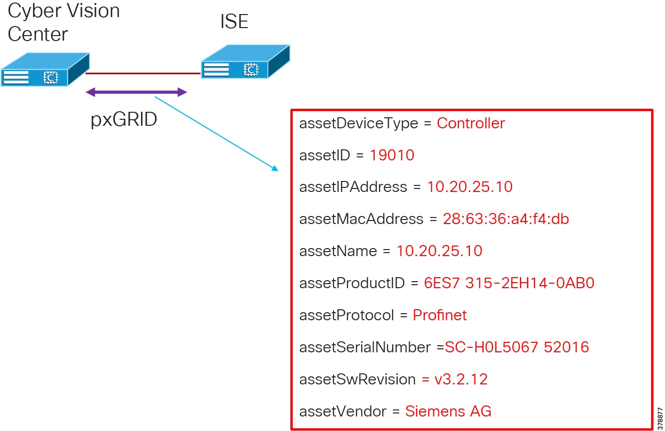
The integration between the Cisco Cyber Vision and ISE provides the following benefits:
■![]() Automatically enrolls IACS assets into the ISE endpoint database.
Automatically enrolls IACS assets into the ISE endpoint database.
■![]() Enables an OT-IT security administrative team to create granular profiling policies based on the attributes received from Cisco Cyber Vision.
Enables an OT-IT security administrative team to create granular profiling policies based on the attributes received from Cisco Cyber Vision.
■![]() Allows the OT engineers to leverage the integration between Cisco Cyber Vision and ISE to automatically deploy new security policies in the network.
Allows the OT engineers to leverage the integration between Cisco Cyber Vision and ISE to automatically deploy new security policies in the network.
Comparison of Cisco Cyber Vision, Cisco Industrial Network Director, and Cisco Stealthwatch
The security for an industrial network covers various aspects and Cisco's approach is to provide a full spectrum of coverage. Cisco offers Cisco Cyber Vision, Cisco Industrial Network Director, and Cisco Stealthwatch, which are complementary technologies which, with Cisco Identity Services Engine, provide an effective combination for broad coverage.
Cisco Stealthwatch covers malware, zero day worms, and other enterprise IT threats.
| Cisco Cyber Vison | Cisco Industrial Network Director | Cisco Stealthwatch | |
|---|---|---|---|
| What is it? | Cisco Cyber Vision is a cybersecurity solution specifically designed to ensure continuity, resilience, and safety of industrial operations. It monitors industrial assets and application flows to extend IT security to the OT domain through easy deployment within the industrial network. | The Cisco IND provides operations-centric network management for industrial Ethernet networks. The system supports industrial automation protocols such as CIP, PROFINET, OPC-UA, Modbus, BACnet, and so on to discover automation devices such as PLC, IO, HMI. It drives and delivers an integrated topology map of automation and networking assets to provide a common framework for operations and plant IT personnel to manage and maintain the industrial network. Provides OT with a user-friendly active scanning network monitoring solution. IND integrates with ISE pxGrid to provide device context details used in profiling for TrustSec segmentation. The pxGrid integration also allows OT staff to enforce security policies by updating asset attributes based on operational intent. | Cisco Stealthwatch provides enterprise-wide network visibility and applies advanced security analytics to detect and respond to threats in real time. Using a combination of behavioral modeling, machine learning, and global threat intelligence, Stealthwatch can quickly, and with high confidence, detect threats such as command-and-control (C&C) attacks, ransomware, distributed-denial-of-service (DDoS) attacks, illicit cryptomining, unknown malware, and insider threats. With a single, agentless solution, you get comprehensive threat monitoring across the entire network traffic, even if it is encrypted. |
| Discovery Method | Passive | Active Scanning | Passive |
| Focus Area | Focused on industrial networks and protocols. This would roughly correlate to level 0 to 2 in the Purdue model. | Focused on industrial networks and protocols at level 0 to 2 in the Purdue model. | Focused on Enterprise IT networks. This would correspond to level 3 to 5 in the Purdue model. The packets must have IP addresses. |
Active and Passive Discovery
There are two approaches to network vulnerability discovery, active and passive. The active approach encompasses everything an organization does to foil system breaches, while the passive (or monitoring) approach entails all the ways the organization oversees system security. It is a mistake to think that you have to choose between the two types of protection.
The passive approach allows security personnel to monitor which operating systems are in use; what is being sent to, from, and within the system; which services are available; and where parts of the system may be vulnerable to security threats. The active approach, on the other hand, offers more information about system and application vulnerabilities.
In short, the two types of discovery/scanner methods complement each other. Characteristics of Passive and Active Scanning describes the characteristics of the two discovery mechanisms.
| Characteristic | Passive | Active |
|---|---|---|
| Potential of Network Impact | Low—Passive discovery does not quiz the asset and merely inspects the packets, behaving as a passive observer. The packets do have to be duplicated in order to observe them. One precaution is to ensure that the duplication of observed traffic does not over-subscribe the available bandwidth of the network. There are simple architectural solutions to ensure that this does not happen. Cisco has a very effective strategy with network devices and Cisco Cyber Vision. Essentially the passive discovery sensor will be available within the network element and traffic will not need to be duplicated on the network. | Medium—Active scanning may adversely affect the asset or network. Hence be cautious when using active scanning methods. Certain scanning tools can perform tests against all TCP protocols and cause tremendous load on the asset and the network. In a production environment, active scanning and especially repeated active scanning may increase the risk of production impacts. Manage the frequency of pings or quiz packets to the devices. Some old controllers and devices may not handle PING/ARP packets efficiently. The best approach is to devise operational methods to contain the risk. For example, active scans can be carried out during production planned downtimes, limited to a very contained subnet, and so on. |
| Completeness of Asset Discovery | Very Effective—If an asset is communicating any packets, then it will be discovered. Of course this depends on the sensor element of the passive scanner being able to see the packet. So effective placement of sensors is very important. An asset that neither sends nor receives any packets will not be discovered. | Variable—Some assets are offline during scans and will not be discovered. ACLs may prevent the quiz packets (for example SNMP) from reaching the asset or the subnet and cause the asset not to be discovered. This is one reason why multiple scans are run, however one need to balance the risk of disruption. The completeness of discovery is highly dependent on the design of the network, ACLs, and whether assets are on-line and responsive to the quiz packets. Another challenge is that as new devices come on-line, unless an active scan is run, it may take some time before such an asset is discovered. |
| Completeness of Asset Information | Indeterministic—Passive discovery by its nature can only determine information that is transmitted by the asset. Some information may not be emitted for a long time and remain undiscovered. For example, one may know that there is a Rockwell PLC, but the version of the firmware of that PLC may not be known until a specific command caused a packet with the firmware version to be transmitted. | Highly deterministic—if an asset is online and reachable and it responds to the quiz commands, then everything pertinent about the asset is discoverable. If an asset is not online or does not respond to all the quiz requests, then it can be marked as "not responsive". But in either case, operators can have very high confidence in knowing what they know and what they do not know. |
| Timeliness of Asset information | Takes time to build a complete picture. Asset discovery of active assets can be instantaneous, i.e. the moment they transmit a packet. However getting a complete picture of the asset can take time, as the passive scanner needs to wait for the relevant packets to be transmitted that contain the necessary information to complete the picture. This can be speeded up by operators instigating benign pings to the asset. | On Demand—with active scanning an asset can be quizzed on demand. However indiscriminate quizzing can cause unintended issues with the asset. It could get inundated and perceive it as a Denial-of-Service attack. |
| Vulnerability Monitoring and Attack Simulation | Passive discovery is focused on vulnerability monitoring exclusively. It does not do any simulation of attack. | Active scanners can simulate attack, however one has to be cautious in such simulations. |
| Cisco Products | Currently Cisco Cyber Vision focuses on passive scanning. Cisco Stealthwatch is also a passive monitor. | Cisco Industrial Network Director focuses on active scanning in addition to network management. |
Cell/Area Zone Security
Digital transformation initiatives in the plant are changing the dimension of traditional OT. Newer networking technologies and COTS hardware and software are replacing legacy products and newer business initiatives are forging a movement towards IT/OT convergence. Technology itself cannot address the entire security realm; people and process must play a critical part in addressing the cybersecurity threat. This is key when addressing OT security. The IT teams need to have a thorough understanding of the business requirements and processes that apply within the industrial environment and assist with implementation. This is extremely relevant in the Cell/Area Zone where traditional IT skillsets are limited and the IT and OT teams need to move away from the traditional siloed approach to network management and work together. A 2015 Gartner study found security can be enhanced if IT security teams are shared, seconded, or combined with OT staff to plan a holistic security strategy.
Security in the Cell/Area Zone needs to be viewed as a component of an overall end-to-end security architecture within the plant. Any security capability needs to span the breadth of the plant and must encompass existing processes and strategy linked to an overall compliance effort while supporting the safety, 24 hours a day, 7 days a week availability, and high OEE requirements of the plant.
This section addresses network hardening for the Cell/Area Zone and basic segmentation and restricted data flow techniques with VLAN segmentation. The evolution of this baseline security features to a more robust, scalable security architecture is addressed in OT Intent-based Security for Industrial Automation Use Cases, which focuses on asset visibility with Cisco Cyber Vision, segmentation using TrustSec with Cisco ISE, and flow-based anomaly detection with Cisco Stealthwatch.
Restricted Data Flow Segmentation and Zoning
Segmentation is a key component to creating zones of trust to help protect IACS networks and processes. IEC 62443 details restricted data flow recommendations to segment the control system into zones and conduits to limit the unnecessary flow of data between process networks or services. Intentional or accidental cross-pollination of traffic between untrusted entities must be restricted. The Industrial Automation solution provides basic logical isolation guidance for segmenting the Cell/Area Zone traffic. Some plants may segment the networks into totally physically separate networks based on risk. For example, plants may provide a physically separate dedicated network for non-operational multiservice type applications such as voice services within the plant.
Within typical plant networks zones are defined as Cell/Area (Level 0-2), Industrial Operations and Control (Level 3), IDMZ and the Enterprise (Level 5). For Cell/Area Zone, further segmentation will apply to grouped IACS assets that need to communicate with each other, generally per cell or area. VLAN segmentation is the traditional approach that has been adopted to creating segmentation across the Cell/Area Zone. The VLAN will be defined for a group of devices that need to communicate with each other within the Layer 2 domain/subnet and a boundary device such as a Layer 3 router, switch, or firewall will allow or deny communications outside of the VLAN to provide inter-cell/area communication such as controller-to-oontroller communication or controller-to-IACS applications. The boundary device can apply access control between the VLANs or Cell/Area and other areas of the plant using traditional ACLs or firewall rules manually configured on the device deployed at the boundary. The Layer 3 distribution switch can provide this functionality and become a policy enforcement point for the Cell/Area Zone.
Figure 49 Cell/Area Zone Layer 3 Distribution Boundary Device
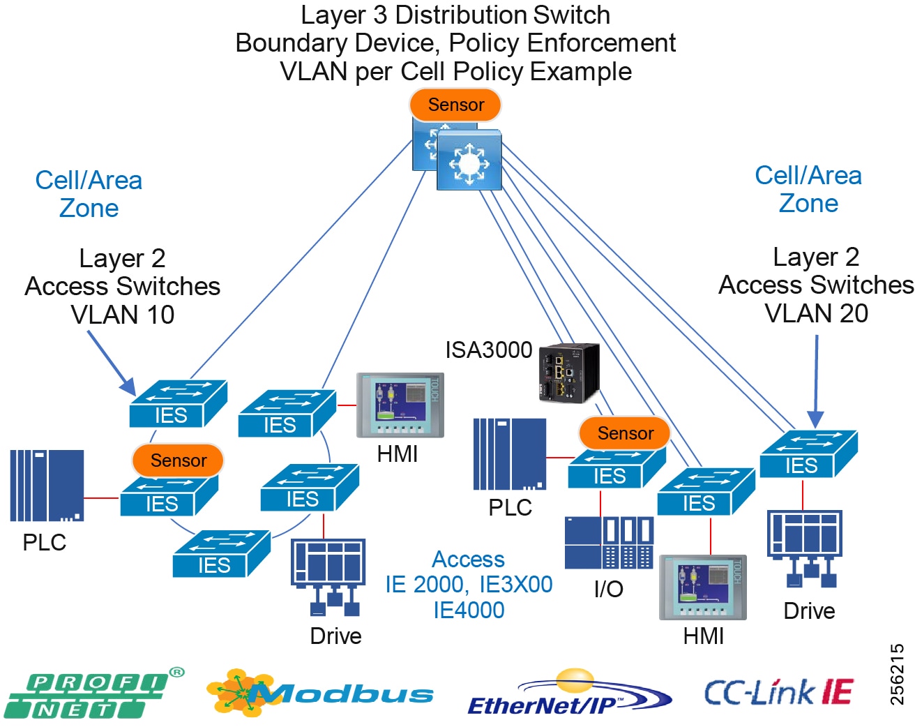
VLAN segmentation and ACLs have been the traditional way to provide restricted dataflow within IACS networks. ACLs can be deployed at the distribution switch or using a Cisco Industrial Firewall Appliance—ISA3000.
ISA3000 is an appliance that provides OT-targeted protection based on proven enterprise class security. This firewall is ideal for IACS applications where trusted zone segmentation is required. It provides the anchor point for converging IT and OT security visibility without interfering with industrial operational practice. Manufacturers can improve security and gain visibility with the IFW's ability to track OT application behavior for industrial protocols such as CIP and abnormal traffic patterns and malicious attacks. To obtain more information about the Cisco ISA3000, go to:
https://www.cisco.com/c/en/us/td/docs/solutions/Verticals/CPwE/5-0/Firewalls/DIG/CPwE-5-IFS-DIG/CPwE-5-IFS-DIG2.html
While manageable for smaller plants, maintaining access policies can be cumbersome and difficult for larger plants. As more devices are added to a network, ACLs start to become large at policy enforcement points and are implemented at various places in the network, making it a distributed application of policy across an industrial plant. Continually updating ACLs poses a higher risk of misconfiguration and is generally not scalable. OT Intent-based Security for Industrial Automation Use Cases details the use cases and evolution to a TrustSec architecture that helps enhance security for industrial automation networks.
Network Hardening—A Component of System Integrity
System hardening, within the realms of cybersecurity, can be defined as reducing the attack surface or vulnerability of a system and making it more resilient to attack through hardening measures. Hardening activities include disabling unnecessary services and applications, providing least-privilege user access to systems, and adding additional security features such as anti-malware, anti-virus, and endpoint security. General system hardening practices apply to networks as well. Network hardening will deploy least privilege access control, disabling or removing unused services, logging, and enabling secure protocols. These hardening features and functions need to be configured across the three functional planes within a networking system. These three functional planes are the Management Plane, the Control Plane and the Data Plane.
■![]() Management Plane-The management plane provides access to the networking devices and consists of functions that provide management of the networking system. The management plane is used to access, configure, and manage a device, as well as monitor its operations and the network on which it is deployed. This includes interactive management sessions that use SSH, as well as statistics gathering with SNMP or NetFlow. When you consider the security of a network device, it is critical that the management plane be protected. If a security incident undermines the functions of the management plane, it may be impossible for you to recover or stabilize the network. Where possible an out-of-band network for network management should be deployed. This keeps network management traffic separated from IACS traffic, which has the advantage of keeping the device reachability independent of any issues that may be occurring in the IACS network. If an out-of-band network is not possible, a logically separated network using a dedicated network management VLAN should be utilized.
Management Plane-The management plane provides access to the networking devices and consists of functions that provide management of the networking system. The management plane is used to access, configure, and manage a device, as well as monitor its operations and the network on which it is deployed. This includes interactive management sessions that use SSH, as well as statistics gathering with SNMP or NetFlow. When you consider the security of a network device, it is critical that the management plane be protected. If a security incident undermines the functions of the management plane, it may be impossible for you to recover or stabilize the network. Where possible an out-of-band network for network management should be deployed. This keeps network management traffic separated from IACS traffic, which has the advantage of keeping the device reachability independent of any issues that may be occurring in the IACS network. If an out-of-band network is not possible, a logically separated network using a dedicated network management VLAN should be utilized.
■![]() Control Plane-The control plane of a network device processes the traffic that is paramount to maintain the functionality of the network infrastructure. The control plane consists of applications and protocols between network devices, which includes the routing protocols and Layer 2 protocols such as REP. It is important that events in the management and data planes do not adversely affect the control plane. Should a data plane event such as a denial of service (DoS) attack impact the control plane, the entire network could become unstable. It should also be stated that control plane traffic needs to be understood and protected so that abnormalities do not affect the performance of the network devices' CPUs, thus making the networking device unstable and therefore creating/contributing to network-wide instability.
Control Plane-The control plane of a network device processes the traffic that is paramount to maintain the functionality of the network infrastructure. The control plane consists of applications and protocols between network devices, which includes the routing protocols and Layer 2 protocols such as REP. It is important that events in the management and data planes do not adversely affect the control plane. Should a data plane event such as a denial of service (DoS) attack impact the control plane, the entire network could become unstable. It should also be stated that control plane traffic needs to be understood and protected so that abnormalities do not affect the performance of the network devices' CPUs, thus making the networking device unstable and therefore creating/contributing to network-wide instability.
■![]() Data Plane-The data plane forwards data throughout a networking system traversing the networking devices. This would be the IACS data traffic between controllers, I/O, HMI, and any other devices plugged into the network. The data plane contains the logical group of "customer" application traffic generated by hosts, clients, servers, and applications that are sourced from and destined to other similar devices supported by the network. Within the context of security, and because the data plane represents the highest traffic rates, it is critical that the data plane be secured to prevent exception packets from punting to the CPU and impacting the control and management planes.
Data Plane-The data plane forwards data throughout a networking system traversing the networking devices. This would be the IACS data traffic between controllers, I/O, HMI, and any other devices plugged into the network. The data plane contains the logical group of "customer" application traffic generated by hosts, clients, servers, and applications that are sourced from and destined to other similar devices supported by the network. Within the context of security, and because the data plane represents the highest traffic rates, it is critical that the data plane be secured to prevent exception packets from punting to the CPU and impacting the control and management planes.
The following provides best practices for network hardening.
Management Plane
■![]() Dedicated out-of-band network should be deployed throughout the plant including the IDMZ.
Dedicated out-of-band network should be deployed throughout the plant including the IDMZ.
■![]() The AAA framework should be implemented, which is critical in order to secure interactive access to network devices and provides a highly configurable environment that can be tailored based on the needs of the network.
The AAA framework should be implemented, which is critical in order to secure interactive access to network devices and provides a highly configurable environment that can be tailored based on the needs of the network.
■![]() ACLs should be enforced to prevent unauthorized direct communication to network devices.
ACLs should be enforced to prevent unauthorized direct communication to network devices.
■![]() Configure secure networking protocols, such as SSH and SNMP v3, for access to the networking equipment.
Configure secure networking protocols, such as SSH and SNMP v3, for access to the networking equipment.
■![]() Network system logging should be enabled throughout the architecture.
Network system logging should be enabled throughout the architecture.
■![]() All network device configuration should be backed up after initial installation, setup, and following modifications.
All network device configuration should be backed up after initial installation, setup, and following modifications.
Control Plane
■![]() Most routers and switches can protect the CPU from DoS-style attacks through functionality equivalent to Control Plane protection or policing.
Most routers and switches can protect the CPU from DoS-style attacks through functionality equivalent to Control Plane protection or policing.
Switches
■![]() Within switched networks, it is important to protect the overall switched network from instability. Mechanisms are deployed in these types of networks to protect the integrity of the Layer 2 switched domains. For example, STP can be used within these switched domains to help maintain a loop free topology in a redundant Layer 2 infrastructure. Within Layer 2 networks, root devices exist that help provide information about the stability of the network. Guard mechanisms need to be configured so that these root devices are not changed. Bridge Protocol Data Units (BPDU) Guard and Root Guard are examples that should be configured to help protect the Layer 2 domain and prevent Spanning Tree instability.
Within switched networks, it is important to protect the overall switched network from instability. Mechanisms are deployed in these types of networks to protect the integrity of the Layer 2 switched domains. For example, STP can be used within these switched domains to help maintain a loop free topology in a redundant Layer 2 infrastructure. Within Layer 2 networks, root devices exist that help provide information about the stability of the network. Guard mechanisms need to be configured so that these root devices are not changed. Bridge Protocol Data Units (BPDU) Guard and Root Guard are examples that should be configured to help protect the Layer 2 domain and prevent Spanning Tree instability.
Router/Routing Protection/Layer 3 Switches
■![]() Neighbor Authentication-When configured, neighbor authentication occurs whenever routing updates are exchanged between neighbor routers. This authentication ensures that a router receives reliable routing information from a trusted device.
Neighbor Authentication-When configured, neighbor authentication occurs whenever routing updates are exchanged between neighbor routers. This authentication ensures that a router receives reliable routing information from a trusted device.
■![]() Routing Peer Definition-The same dynamic peer discovery mechanisms that facilitate deployment and setup of routers can potentially be used to insert bogus routers into the routing infrastructure. Disabling such dynamic mechanisms by statically configuring a list of trusted neighbors with known IP addresses prevents this problem. This can be used in conjunction with other routing security features such as neighbor authentication and route filtering.
Routing Peer Definition-The same dynamic peer discovery mechanisms that facilitate deployment and setup of routers can potentially be used to insert bogus routers into the routing infrastructure. Disabling such dynamic mechanisms by statically configuring a list of trusted neighbors with known IP addresses prevents this problem. This can be used in conjunction with other routing security features such as neighbor authentication and route filtering.
■![]() Control Plane Policing or Protection-This option should be configured to help protect routing sessions by preventing the establishment of unauthorized sessions, thus reducing the chances for session reset attacks.
Control Plane Policing or Protection-This option should be configured to help protect routing sessions by preventing the establishment of unauthorized sessions, thus reducing the chances for session reset attacks.
Data Plane
■![]() Unused ports—Place any ports not being used into a shutdown state. For the purpose of a switch, add the switchport VLAN command with an unused VLAN (not VLAN 1) so that if a port is accidentally activated, it will not affect any deployed VLANs.
Unused ports—Place any ports not being used into a shutdown state. For the purpose of a switch, add the switchport VLAN command with an unused VLAN (not VLAN 1) so that if a port is accidentally activated, it will not affect any deployed VLANs.
■![]() Port security limits the number of MACs on a particular interface. This helps to prevent threats such as MAC attacks. Port security should be enabled on switch access ports.
Port security limits the number of MACs on a particular interface. This helps to prevent threats such as MAC attacks. Port security should be enabled on switch access ports.
■![]() DHCP snooping—If servers or workstations in the architecture are using DHCP, then DHCP snooping and Dynamic ARP Inspection (DAI) should be considered.
DHCP snooping—If servers or workstations in the architecture are using DHCP, then DHCP snooping and Dynamic ARP Inspection (DAI) should be considered.
■![]() Traffic Storm Control—A traffic storm occurs when packets flood the LAN, creating excessive traffic and degrading network performance. The traffic storm control feature can be used to prevent disruptions on Ethernet interfaces by a broadcast, multicast, or unknown unicast traffic storm.
Traffic Storm Control—A traffic storm occurs when packets flood the LAN, creating excessive traffic and degrading network performance. The traffic storm control feature can be used to prevent disruptions on Ethernet interfaces by a broadcast, multicast, or unknown unicast traffic storm.
VLAN Best Practices
■![]() Disable all unused ports and put them in an unused VLAN. Any enabled open port provides an access medium into the network.
Disable all unused ports and put them in an unused VLAN. Any enabled open port provides an access medium into the network.
■![]() Do not use VLAN 1 for anything. VLAN 1 is the default VLAN and is enabled on all ports by default; therefore, it is a security best practice to configure all the ports on all switches to be associated with VLANs other than VLAN 1.
Do not use VLAN 1 for anything. VLAN 1 is the default VLAN and is enabled on all ports by default; therefore, it is a security best practice to configure all the ports on all switches to be associated with VLANs other than VLAN 1.
■![]() To assist with preventing VLAN hopping attacks, whereby an end station can spoof as a switch, configure all user-facing ports as non-trunking. Force tagging for the native VLAN on trunks and drop untagged frames to assist with preventing VLAN hopping.
To assist with preventing VLAN hopping attacks, whereby an end station can spoof as a switch, configure all user-facing ports as non-trunking. Force tagging for the native VLAN on trunks and drop untagged frames to assist with preventing VLAN hopping.
■![]() Explicitly configure trunking on infrastructure ports. For ports connecting switches, trunking is used to extend VLANs throughout the network. Explicitly configure only the VLANs required to be extended to other switches.
Explicitly configure trunking on infrastructure ports. For ports connecting switches, trunking is used to extend VLANs throughout the network. Explicitly configure only the VLANs required to be extended to other switches.
Note: DHCP snooping or Dynamic Advance Resolution Protocol (ARP) inspection utilizes IP Device Tracking. Certain industrial environments are susceptible to issues when IP device tracking is enabled. Follow the design best practices for IP device tracking as detailed in OT Intent-based Security for Industrial Automation Use Cases.
OT Intent-Based Networking Security
Industrial plant networks are less immune to malware propagation as compared to enterprise networks. For example, the PLC blaster worm (Ralf Spenneberg, n.d.) demonstrated in a lab how a vulnerability in a PLC can be exploited by a worm and once the PLC is infected with a worm it can discover other vulnerable devices (PLCs) in the network and replicate itself on those discovered targets. Even though this attack was demonstrated in a lab, it shows how malware can attack IACS devices if there are not adequate security protections such as asset visibility, traffic segmentation, malware detection and remediation of infected devices, and OT intent-based control mechanisms deployed in a plant floor.
To prevent malware such as PLC blaster from attacking the industrial plant, the following must be considered:
■![]() Gain visibility of all IACS devices and communication present on a plant floor. Knowing which devices are present and active in a network and who they are talking to will be vitally important to designing a policy which controls device communication. For example, if a PLC attached to a network is visible, then a security policy can be designed to protect that PLC.
Gain visibility of all IACS devices and communication present on a plant floor. Knowing which devices are present and active in a network and who they are talking to will be vitally important to designing a policy which controls device communication. For example, if a PLC attached to a network is visible, then a security policy can be designed to protect that PLC.
■![]() Restrict communications of devices on the plant floor. If a PLC is only able to communicate with a finite number of devices, then a potential threat surface can be reduced.
Restrict communications of devices on the plant floor. If a PLC is only able to communicate with a finite number of devices, then a potential threat surface can be reduced.
■![]() Detecting malware spreading in a network. One behavior of the PLC blaster worm is to scan the network and discover other vulnerable devices. The key defense strategy is to discover that a scan is happening in the network where unexpected and plan a remediation action plan.
Detecting malware spreading in a network. One behavior of the PLC blaster worm is to scan the network and discover other vulnerable devices. The key defense strategy is to discover that a scan is happening in the network where unexpected and plan a remediation action plan.
■![]() Restrict remote access to devices. When an IACS device is down or needs advanced troubleshooting, then in some situations a remote expert may need to access the device and do further analysis. The operations team should determine appropriate device accessibility for the remote troubleshooter.
Restrict remote access to devices. When an IACS device is down or needs advanced troubleshooting, then in some situations a remote expert may need to access the device and do further analysis. The operations team should determine appropriate device accessibility for the remote troubleshooter.
Note: Cisco and Rockwell Automation jointly designed and validated OT Intent-Based Network Security for EtherNet/IP based devices. See the CPwE Network CVD listed in Previous and Related Documentation for more information.
This section describes the following:
■![]() IACS plant security reference architecture
IACS plant security reference architecture
■![]() System components overview
System components overview
■![]() Cell/Area Zone
Cell/Area Zone
■![]() Design considerations for deploying network security in Cell/Area Zone
Design considerations for deploying network security in Cell/Area Zone
Plantwide Security Reference Architecture
Figure 50 provides a plantwide view of security and suggested areas of responsibility for deploying security. This highlights collaboration between control system engineers, IT network engineers, and IT security architects.
Figure 50 Plantwide View of Security and Areas of Responsibility
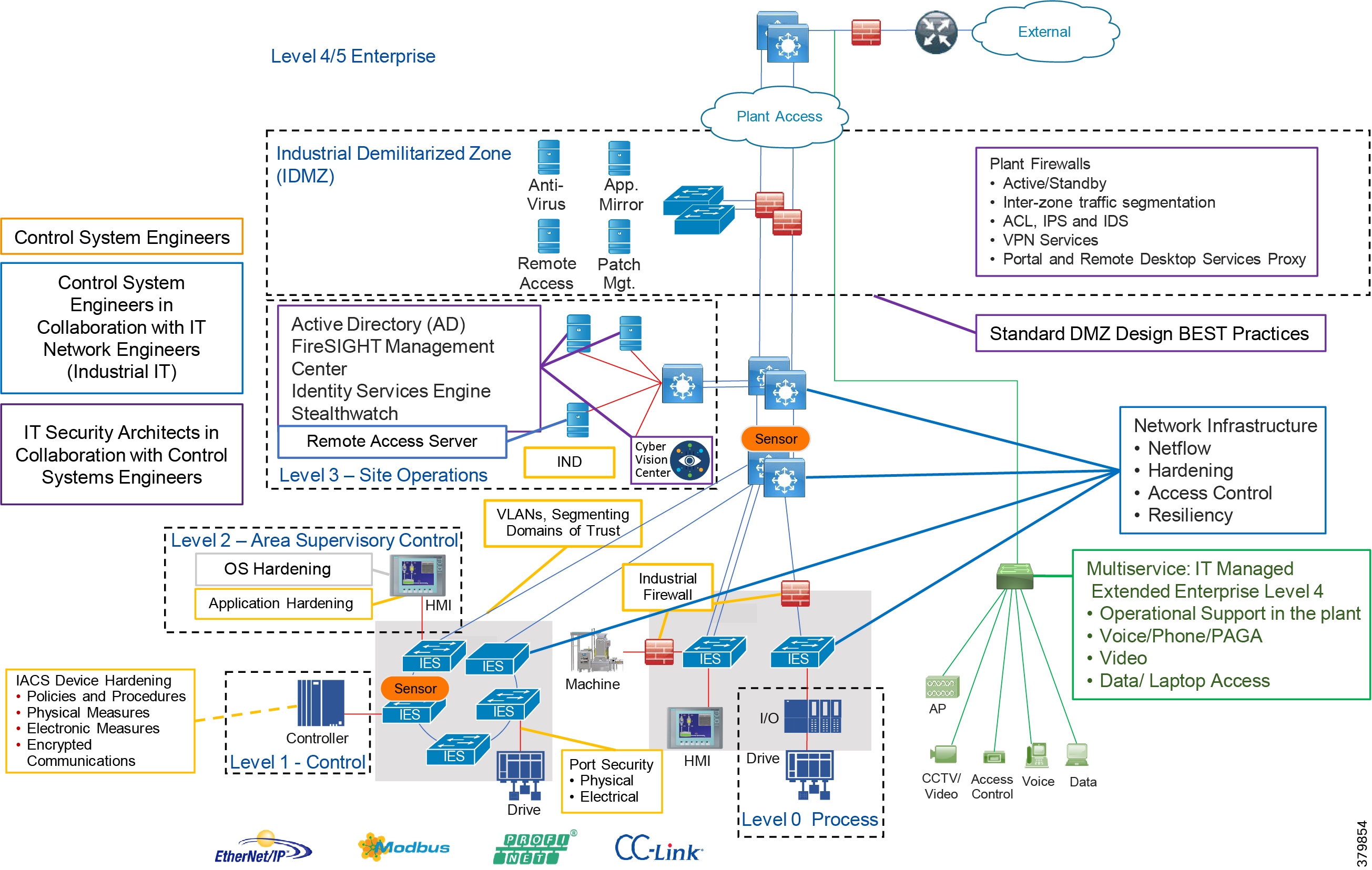
The CPwE CVD defined personae for the security architecture. The following provides details aligned with the figures above.
■![]() Control System Engineers (highlighted in tan)-IACS asset hardening (for example, physical and electronic), infrastructure device hardening (for example, port security), network monitoring and change management, network segmentation (trust zoning), industrial firewalls (with inspection) at the IACS application edge, and IACS application AAA.
Control System Engineers (highlighted in tan)-IACS asset hardening (for example, physical and electronic), infrastructure device hardening (for example, port security), network monitoring and change management, network segmentation (trust zoning), industrial firewalls (with inspection) at the IACS application edge, and IACS application AAA.
■![]() Control System Engineers in collaboration with IT Network (highlighted in blue)-Computer hardening (OS patching, application white listing), network device hardening (for example, access control, resiliency), network monitoring and inspection, and wired and wireless LAN access policies.
Control System Engineers in collaboration with IT Network (highlighted in blue)-Computer hardening (OS patching, application white listing), network device hardening (for example, access control, resiliency), network monitoring and inspection, and wired and wireless LAN access policies.
■![]() IT Security Architects in collaboration with Control Systems Engineers (highlighted in purple)-Identity and Mobility Services (wired and wireless), network monitoring with anomaly detection, Active Directory (AD), Remote Access Servers, plant firewalls, and IDMZ design best practices.
IT Security Architects in collaboration with Control Systems Engineers (highlighted in purple)-Identity and Mobility Services (wired and wireless), network monitoring with anomaly detection, Active Directory (AD), Remote Access Servers, plant firewalls, and IDMZ design best practices.
Standardization plays an important role in helping to provide an overall security strategy to align people process and technology. A security risk assessment is a key step and will help define which systems are critical control, non-critical control, and non-operational to assist with defining an overall security architecture while still meeting business and safety requirements. Risk assessment guidelines are provided in IEC 62443-3-2. Once the risk has been assessed, foundational security requirements as defined in IEC 62443-3-3 can provide guidance in securing the industrial control system. The DIG for the Industrial Automation program aligns with these foundational requirements:
■![]() FR1 Identification and Authentication Control-Identify and authenticate all users (humans, software processes, and devices) before allowing them to access to the control system.
FR1 Identification and Authentication Control-Identify and authenticate all users (humans, software processes, and devices) before allowing them to access to the control system.
■![]() FR2 Use Control-Enforce the assigned privileges of an authenticated user to perform the requested action on the IACS and monitor the use of these privileges.
FR2 Use Control-Enforce the assigned privileges of an authenticated user to perform the requested action on the IACS and monitor the use of these privileges.
■![]() FR3 System Integrity-Ensure the integrity of the IACS to prevent unauthorized manipulation.
FR3 System Integrity-Ensure the integrity of the IACS to prevent unauthorized manipulation.
■![]() FR4 Data Confidentiality-Ensure the confidentiality of information on the communications network and in storage. This may include methods such as segmentation, protecting against unauthorized access, and data encryption.
FR4 Data Confidentiality-Ensure the confidentiality of information on the communications network and in storage. This may include methods such as segmentation, protecting against unauthorized access, and data encryption.
■![]() FR5 Restricted Dataflow-Use segmentation and zones to provide isolation for each environment and conduits to limit the unnecessary flow of data between zones and architectural tiers.
FR5 Restricted Dataflow-Use segmentation and zones to provide isolation for each environment and conduits to limit the unnecessary flow of data between zones and architectural tiers.
■![]() FR6 Timely Response to Events-Manage, monitor, log, and control the security of the infrastructure to identify, defend, and prevent any security threats or breaches including management audit, logging, and threat detection.
FR6 Timely Response to Events-Manage, monitor, log, and control the security of the infrastructure to identify, defend, and prevent any security threats or breaches including management audit, logging, and threat detection.
■![]() FR7 Resources Availability-Ensure the availability of the control system against the degradation or denial of essential services.
FR7 Resources Availability-Ensure the availability of the control system against the degradation or denial of essential services.
System Components Overview
The following Cisco security components assist in helping secure the Cell/Area Zone.
Cisco Cyber Vision
Cisco Cyber Vision has two primary components: Center and Sensor. The Sensor uses deep packet inspection (DPI) to filter the packets and extract metadata, which is sent to the Center for further analytics. Deep packet inspection is a sophisticated process of inspecting packets including the application layer to discover any abnormal behavior occurring in the network. The Sensor sends only metadata information to the center, which prevents overloading the network traffic.
Cisco Cyber Vision Center
Cisco Cyber Vision Center is an application that can be installed as a virtual machine or as a hardware appliance. The Center provides easy-to-follow visualization that allows an OT operator to gain visibility into the network infrastructure. Figure 51 shows a high-level overview of the Cisco Cyber Vision Center dashboard.
Figure 51 Cisco Cyber Vision Center Dashboard
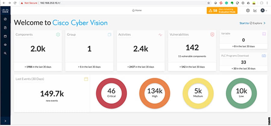
The Center provides the following functions:
■![]() Dynamic inventory—Cisco Cyber Vision Center generates a dynamic inventory of all the IACS devices on the plant floor. As discussed in the Active and Passive Discovery, the Cisco Cyber Vision Sensor continuously listens to the events happening on the plant floor, thereby allowing the Cisco Cyber Vision Center to build and update the dynamic inventory of the devices in the plant floor. The OT operator does not need to perform any scans to get the list of current devices on the plant floor. Also, when a particular device goes offline, the Cisco Cyber Vision Center updates its list dynamically. Figure 52 shows how the Cisco Cyber Vision Center displays the components.
Dynamic inventory—Cisco Cyber Vision Center generates a dynamic inventory of all the IACS devices on the plant floor. As discussed in the Active and Passive Discovery, the Cisco Cyber Vision Sensor continuously listens to the events happening on the plant floor, thereby allowing the Cisco Cyber Vision Center to build and update the dynamic inventory of the devices in the plant floor. The OT operator does not need to perform any scans to get the list of current devices on the plant floor. Also, when a particular device goes offline, the Cisco Cyber Vision Center updates its list dynamically. Figure 52 shows how the Cisco Cyber Vision Center displays the components.
Figure 52 Cisco Cyber Vision Center Dynamic Component Inventory Display
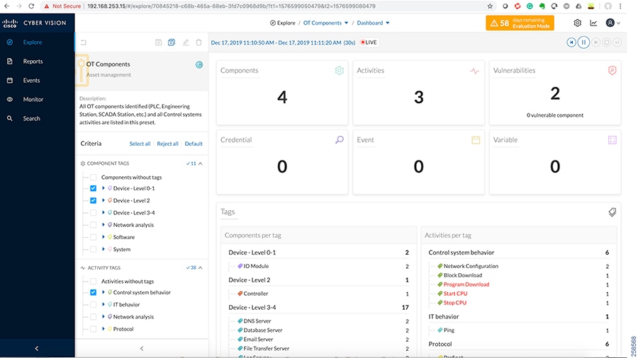
■![]() Intuitive filters—Cisco Cyber Vision Center provides intuitive filters labeled as presets to help an OT operator to look examine data. For example, an operator may want to look at the current list of OT components or process control activities. The Center allows the operator to construct custom filters. Figure 53 depicts the type of presets available in the Cisco Cyber Vision Center.
Intuitive filters—Cisco Cyber Vision Center provides intuitive filters labeled as presets to help an OT operator to look examine data. For example, an operator may want to look at the current list of OT components or process control activities. The Center allows the operator to construct custom filters. Figure 53 depicts the type of presets available in the Cisco Cyber Vision Center.
Figure 53 Cisco Cyber Vision Center Presets
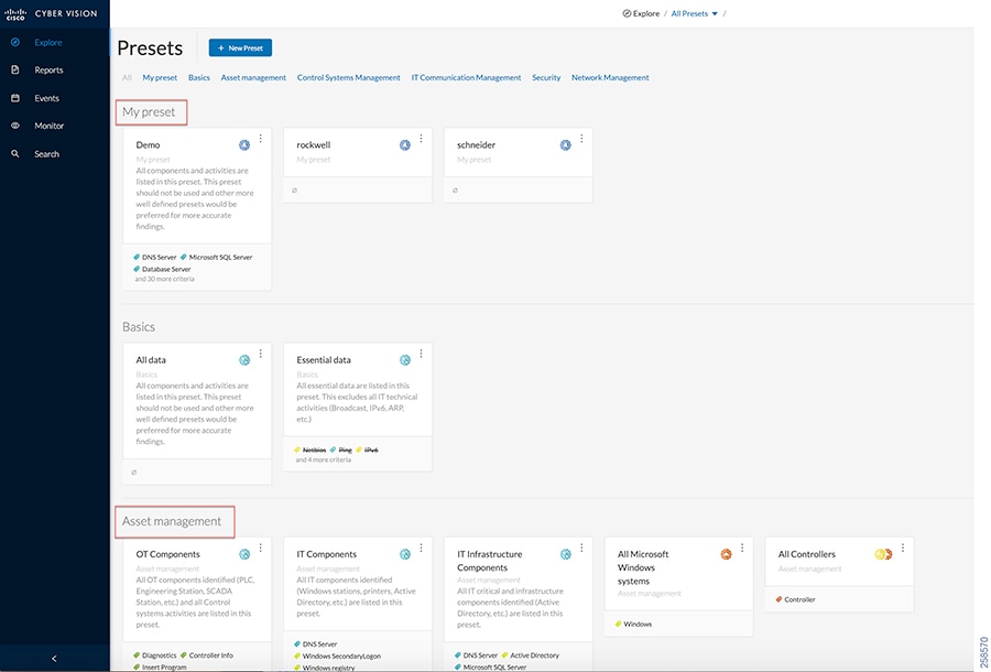
■![]() Detailed IACS asset information—One of the significant advantages of the Cisco Cyber Vision solution is the ability to glean very detailed information about IACS assets. Figure 54 displays information about a Siemens controller.
Detailed IACS asset information—One of the significant advantages of the Cisco Cyber Vision solution is the ability to glean very detailed information about IACS assets. Figure 54 displays information about a Siemens controller.
Figure 54 Example of Detailed Asset Information for Siemens Controller
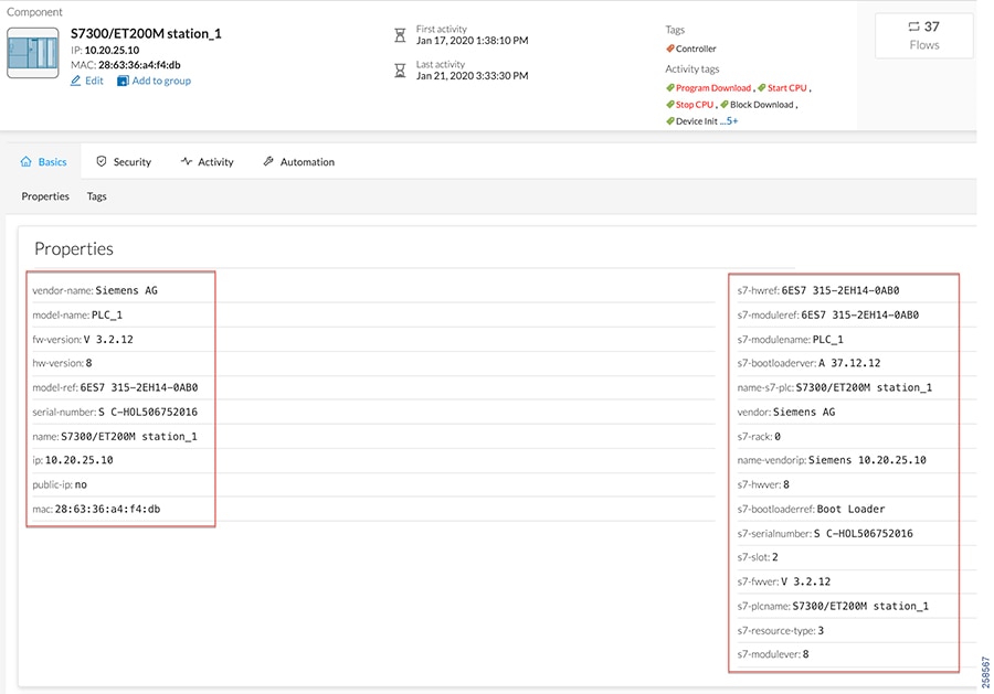
■![]() Dynamic maps—Cisco Cyber Vision Center provides very detailed maps that display the components and the communication flows between them. Figure 55 depicts how Cisco Cyber Vision displays the network map.
Dynamic maps—Cisco Cyber Vision Center provides very detailed maps that display the components and the communication flows between them. Figure 55 depicts how Cisco Cyber Vision displays the network map.
Figure 55 Cisco Cyber Vision Network Map
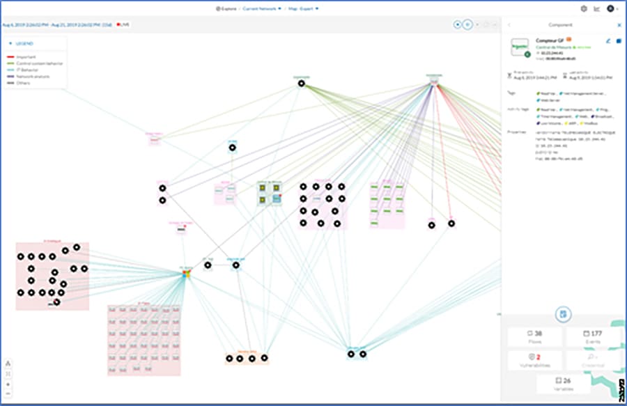
■![]() Baselining—Cisco Cyber Vision Center supports a feature called baselining, which allows an operator to select a set of components to monitor. After a baseline is defined, the operator can compare the changes that happened to this set of elements at different time instants.
Baselining—Cisco Cyber Vision Center supports a feature called baselining, which allows an operator to select a set of components to monitor. After a baseline is defined, the operator can compare the changes that happened to this set of elements at different time instants.
■![]() Vulnerability management—Cisco Cyber Vision Center highlights vulnerabilities that are present in IACS devices, which helps an operator to mitigate those vulnerabilities.
Vulnerability management—Cisco Cyber Vision Center highlights vulnerabilities that are present in IACS devices, which helps an operator to mitigate those vulnerabilities.
■![]() Reports—Cisco Cyber Vision allows an operator to generate reports such as inventory, activity, vulnerability, and PLC reports.
Reports—Cisco Cyber Vision allows an operator to generate reports such as inventory, activity, vulnerability, and PLC reports.
Cisco Cyber Vision Sensor
The Cyber Vision Sensor passively monitors operational network traffic and performs deep packet inspection to discover IACS assets, traffic, and vulnerabilities. The sensor forwards metadata such as device attributes, packet headers, and operational events to the Cyber Vision Center, which does not significantly impact network bandwidth utilization. Two interfaces are used by the sensor: one for management communication and a second for data capture. The management interface is used by the Cyber Vision Sensor to send the metadata to the Cyber Vision Center and the capture interface receives SPAN traffic for inspection. It is recommended to configure the management interface with an existing VLAN from the Cell/Area Zone.
In this guide, two types of Cisco Cyber Vision Sensors were validated:
■![]() Hardware sensor—Cisco IC3000 with Cisco Cyber Vision Sensor installed as an IOx application.
Hardware sensor—Cisco IC3000 with Cisco Cyber Vision Sensor installed as an IOx application.
■![]() Network sensor—Cisco Cyber Vision Sensor embedded as an IOx application on the Cisco IE3400 and Catalyst 9300.
Network sensor—Cisco Cyber Vision Sensor embedded as an IOx application on the Cisco IE3400 and Catalyst 9300.
The Cisco IC3000 is an industrial compute platform capable of having four physical interfaces (int1-in4) in addition to the management Ethernet interface (int0). When Cisco IC3000 is deployed as a hardware sensor, the management interface is used to transport the information to the Cisco Cyber Vision Center; the four interfaces are used for data collection. There are two options available to order and deploy Cisco Cyber Vision Sensor using Cisco IC3000:
■![]() A customer may have an existing Cisco IC3000 and wants to install Sensor as an application in the Cisco IC3000.
A customer may have an existing Cisco IC3000 and wants to install Sensor as an application in the Cisco IC3000.
■![]() A customer orders a new Cisco IC3000 that has the Sensor application deployed as an application.
A customer orders a new Cisco IC3000 that has the Sensor application deployed as an application.
Both options are supported, however, the assumption is that in most deployments the Cisco IC3000 with the Sensor application software installed will be the most common. Information on configuring a new Cisco IC3000 ordered with the Cisco Cyber Vision Sensor application is available at:
■![]() Cisco Cyber Vision Sensor Quickstart Guide
Cisco Cyber Vision Sensor Quickstart Guide
https://www.cisco.com/c/dam/en/us/td/docs/security/cyber_vision/Cisco_Cyber_Vision_Sensor_Quickstart_Guide_Release_3_0_0.pdf
If a customer has an existing Cisco IC3000 and wants to deploy the Cisco Cyber Vision Sensor application, then the recommended step is to do a configuration reset of the Cisco IC3000. Refer to the steps in the section "Installing the Cyber Vision Sensor Application Using Local Manager after a Configuration Reset" at the quickstart guide URL above.
The Cyber Vision network sensor is a software-based solution in the Industrial Automation network. The application is the same as the one used in the hardware sensor except that it is implemented in a networking device. The supported platforms that are validated in this CVD are the IE 3400 and Catalyst 9300. The network sensor deployed in the IE 3400 will detect all the intra-cell communication flows and inter-cell communication flows. However, in ring-based topologies an IE 3400 switch may miss a communication flow which is not in its traffic path. Deploying a network sensor in the Catalyst 9300 will detect all the inter-cell communication flows and also any flows that are coming from the higher layers to the Cell/Area Zone, for example, the communication flows coming from the Enterprise Zone to the Cell/Area Zone. There are many advantages in deploying a network-based sensor in your network:
■![]() The operations engineer from the Level 3 Site Operations Zone can install the network sensor and it does not need an OT engineer to visit the Cell/Area Zone.
The operations engineer from the Level 3 Site Operations Zone can install the network sensor and it does not need an OT engineer to visit the Cell/Area Zone.
■![]() The network-based sensor does not have any limitation on the number of physical interfaces it can monitor.
The network-based sensor does not have any limitation on the number of physical interfaces it can monitor.
The recommended option for the customers is to deploy the network sensor on the IE 3400 and Catalyst 9300. It is easier to use and provides all the benefits without additional hardware. However, in brownfield deployments, where it is not possible to upgrade the switches to IE 3400, the hardware sensor can be deployed.
Deployment Considerations
This section discusses the critical design considerations that must be taken into account while deploying Cisco Cyber Vision solutions in industrial automation environments. The Cisco Cyber Vision solution supports two deployment models: offline mode and online mode.
Cisco Cyber Vision Offline Mode
Cisco Cyber Vision offline mode is deployed by an OT engineer when there is no Cisco Cyber Vision Center or there is no Layer 3 communication between the Cisco Cyber Vision Sensor and the Cisco Cyber Vision Center. In these situations, the OT engineer can use offline mode, which involves capturing the data packets using a USB stick and then later analyzing them by manually loading them in the Cisco Cyber Vision Center. This option is used by an OT engineer to perform a proof of concept.
Cisco Cyber Vision Online Mode
Cisco Cyber Vision online mode assumes that there is Layer 3 connectivity between the Cisco Cyber Vision Sensor and the Center. In this guide, we recommend customers use online mode for the following reasons:
■![]() Online mode ensures that the OT and IT operations teams get a continuous update of traffic in real-time.
Online mode ensures that the OT and IT operations teams get a continuous update of traffic in real-time.
■![]() There is no manual process of capturing the data and uploading the data as discussed in offline mode. The data is captured in real-time at the Cisco Cyber Vision Center.
There is no manual process of capturing the data and uploading the data as discussed in offline mode. The data is captured in real-time at the Cisco Cyber Vision Center.
■![]() Offline mode depends on the available storage space of the USB disk and cannot be used as a solution for long term storage of the data.
Offline mode depends on the available storage space of the USB disk and cannot be used as a solution for long term storage of the data.
Figure 56 illustrates how Cisco Cyber Vision solution is deployed in online mode in the Cell/Area Zone.
Figure 56 Online Mode Deployment in Cell/Area Zone
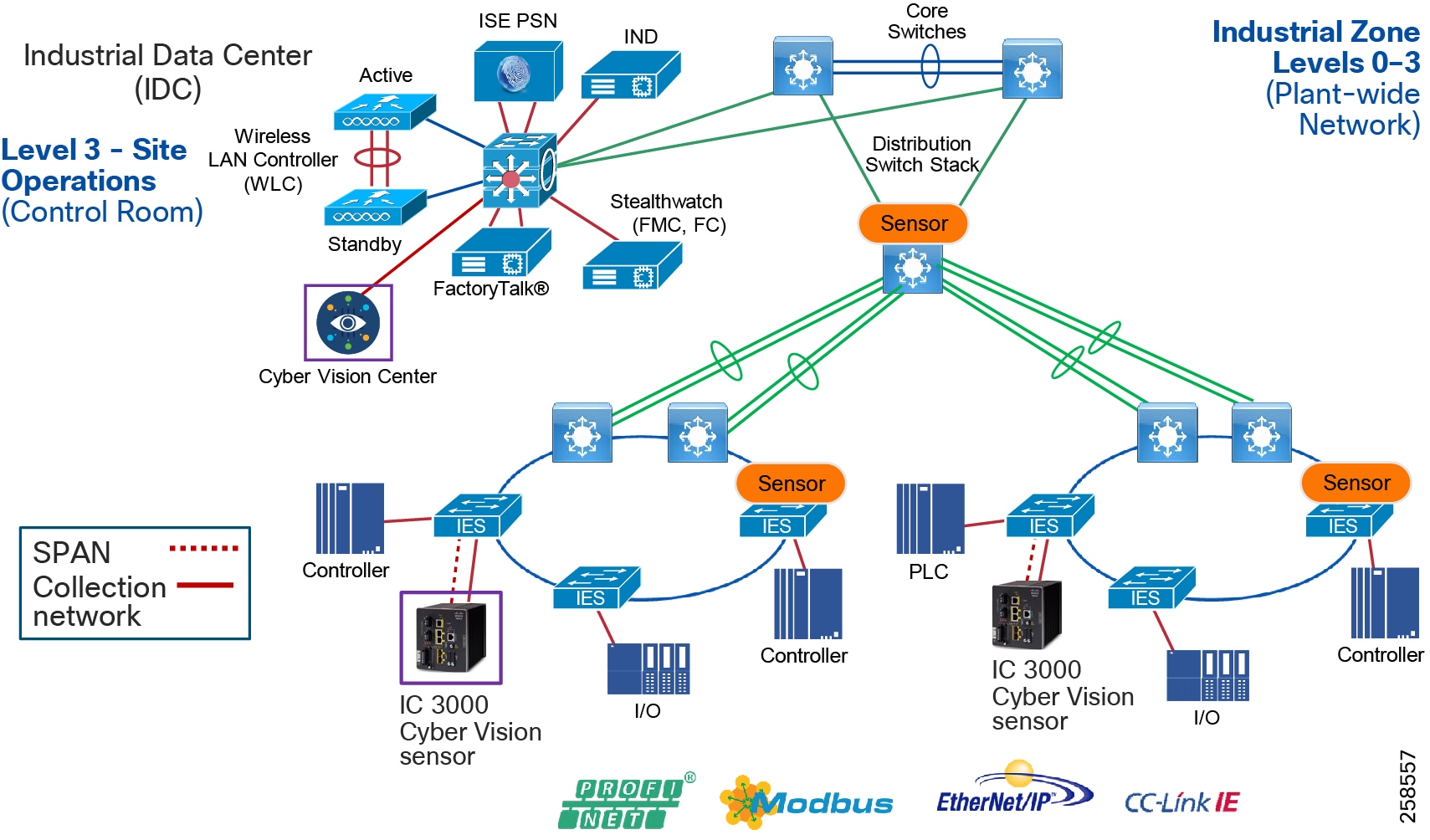
As shown in Figure 56, Cisco IC3000 deployed with Cisco Cyber Vision has two distinct set of interfaces: collection interface and mirror interfaces. The collection is a Layer 3 interface that is used to transport the metadata to the Center. The mirror interfaces collect the SPAN traffic in the network.
Performance
The control system engineer deploying hardware sensor or network sensor must take into account its performance numbers. The critical performance metrics for Cyber Vision Version 3.1.0 are:
■![]() The number of flows supported for a single Cisco IC3000 is15,000 or 12,000 packets per second.
The number of flows supported for a single Cisco IC3000 is15,000 or 12,000 packets per second.
■![]() The sensor on the IE 3400 can support approximately 9,600 packets per second.
The sensor on the IE 3400 can support approximately 9,600 packets per second.
■![]() The sensor on the Catalyst 9300 can support approximately 30,000 packets per second
The sensor on the Catalyst 9300 can support approximately 30,000 packets per second
Location of Sensors in the Network
The control system engineer must be careful when determining the correct location for the sensor in the network. The Cisco Cyber Vision sensor uses deep packet inspection to analyze the traffic flows. The recommendations are:
■![]() When using multiple monitor ports on the Cisco IC3000 sensor, ensure that both ports are part of the same subnet. As shown in Figure 56, the two ring deployments belong to different subnets and, in that scenario, use two separate Cisco IC3000s.
When using multiple monitor ports on the Cisco IC3000 sensor, ensure that both ports are part of the same subnet. As shown in Figure 56, the two ring deployments belong to different subnets and, in that scenario, use two separate Cisco IC3000s.
■![]() Do not span traffic belonging to two routing interfaces to the same Cisco IC3000.
Do not span traffic belonging to two routing interfaces to the same Cisco IC3000.
Capture Points
The effectiveness of the Cisco Cyber Vision solution depends on effectively capturing traffic, so deciding where to capture traffic is critical. There are two types of flows: east-west and north-south as described in Cell/Area Zone Security Design Considerations. Deploying network sensor in the distribution switch using the Catalyst 9300 will capture the north-south traffic. In the Cell/Area Zone, deploying network/hardware sensor at a switch where a controller is attached is an ideal choice to monitor the traffic because all the IO devices respond to the poll requests initiated by the controller. However, there could be scenarios where there are many controller devices attached to several switches in the network, and if you want to monitor the traffic from all those devices, then you have three choices:
■![]() Enable RSPAN on all the switches and direct the monitored traffic to the switch where a hardware or network sensor is installed.
Enable RSPAN on all the switches and direct the monitored traffic to the switch where a hardware or network sensor is installed.
■![]() Enable a local SPAN on each of the switches to be monitored and connect them to a separate switch (only for monitoring), which aggregates the data and sends it to the sensor.
Enable a local SPAN on each of the switches to be monitored and connect them to a separate switch (only for monitoring), which aggregates the data and sends it to the sensor.
■![]() Capture the traffic only at the networking switch where controllers are attached (recommended).
Capture the traffic only at the networking switch where controllers are attached (recommended).
Figure 57 Enable RSPAN on All Switches
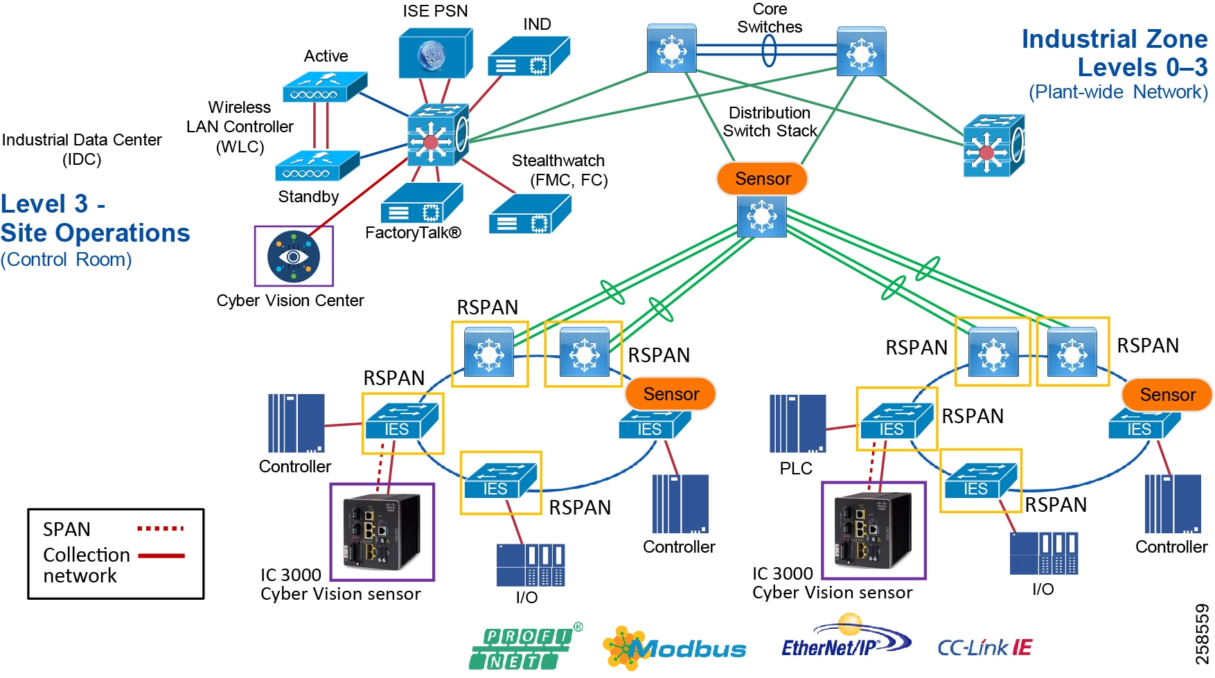
The second option is to aggregate all the SPAN traffic to a SPAN aggregation switch and then direct that traffic to Cisco IC3000 sensor.
Figure 58 Enable Individual RSPAN on Monitored Switches and Connect to Specific Switch
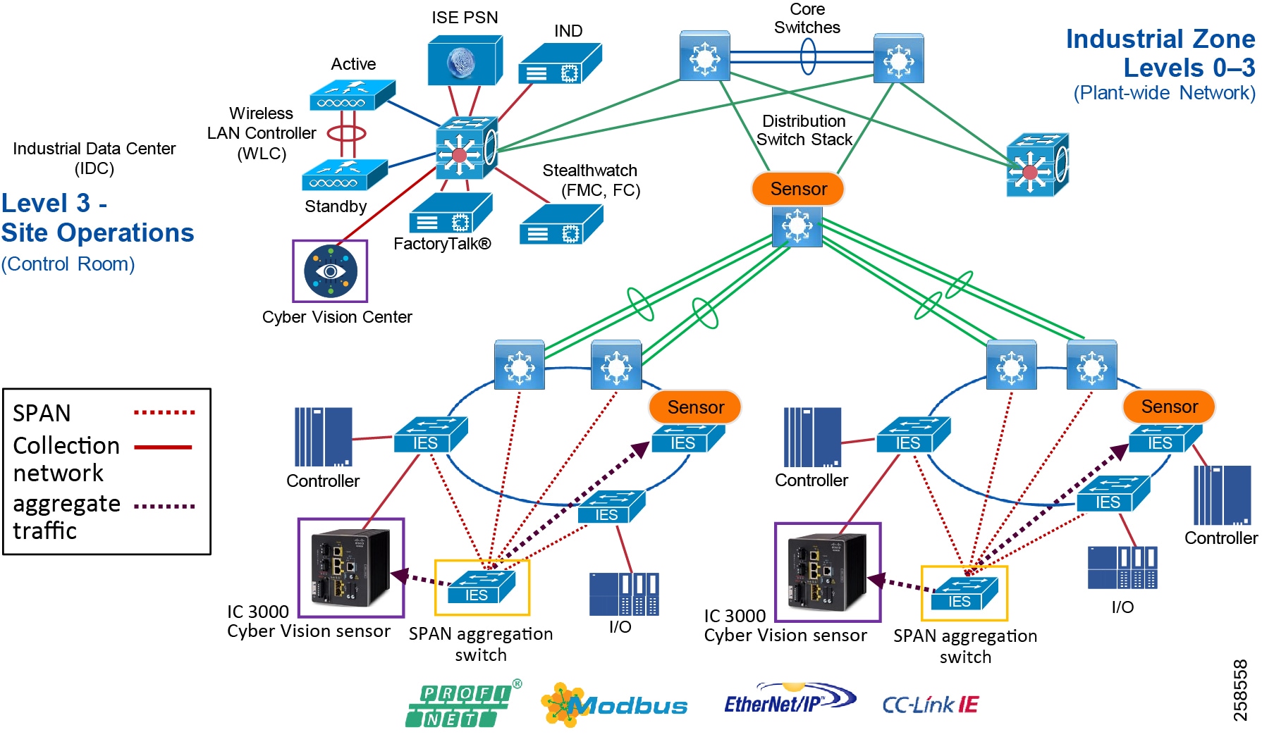
The third option is to enable SPAN at selective points.
Figure 59 Enable SPAN at Selective Points
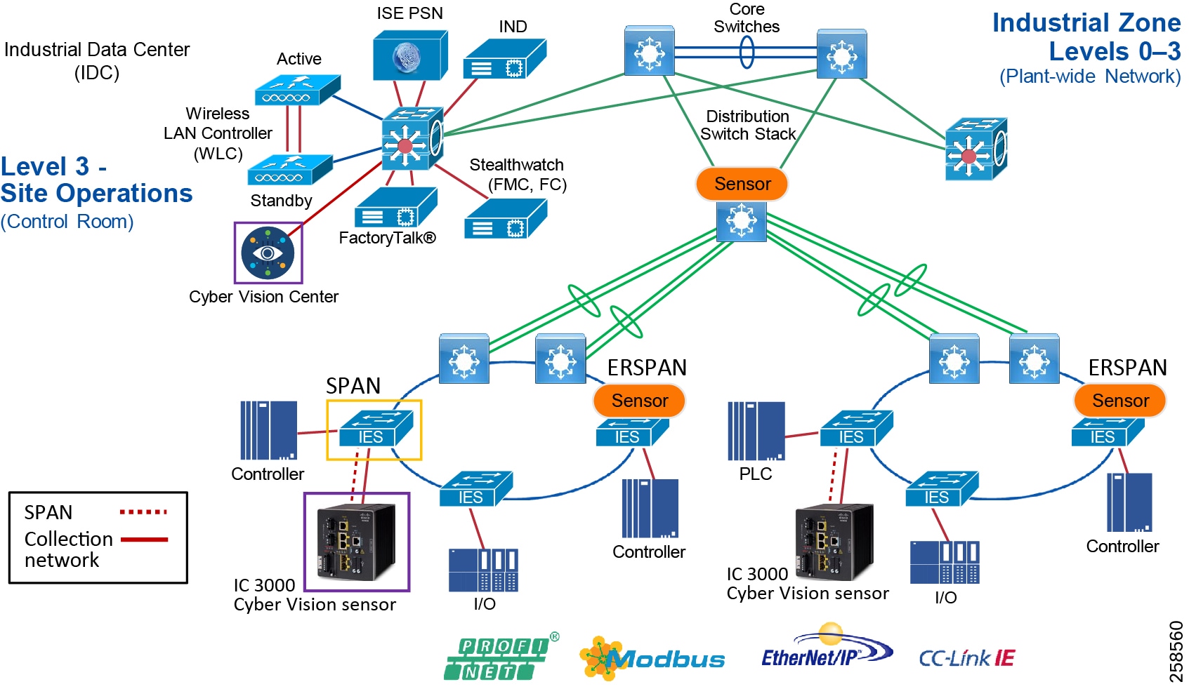
tive Points
The guide recommends initially using the third option for the following reasons:
■![]() The most critical traffic on the plant floor is communication from the PLC to other devices on the plant floor.
The most critical traffic on the plant floor is communication from the PLC to other devices on the plant floor.
■![]() Most security attacks originate by exploiting the vulnerabilities in the PLCs.
Most security attacks originate by exploiting the vulnerabilities in the PLCs.
■![]() If there is a strong need to monitor all the devices, then option 2 is a better choice for deployment.
If there is a strong need to monitor all the devices, then option 2 is a better choice for deployment.
Industrial Network Director
Cisco IND is a network management product for OT team that provides an easily-integrated system delivering increased operator and technician productivity through streamlined network monitoring and rapid troubleshooting. Cisco IND is part of a comprehensive IoT solution from Cisco:
■![]() Easy-to-adopt network management system built specifically for industrial applications that leverages the full capabilities of the Cisco IE switches to make the network accessible to non-IT operations personnel.
Easy-to-adopt network management system built specifically for industrial applications that leverages the full capabilities of the Cisco IE switches to make the network accessible to non-IT operations personnel.
■![]() Creates a dynamic, integrated topology of automation and networking assets using discovery via industrial protocols (CIP, PROFINET) to provide a common framework for OT and IT personnel to monitor and troubleshoot the network and quickly recover from unplanned downtime. The device discovery also provides context details of the connected industrial devices (such as PLCs, I/O, Drives, HMI and so on).
Creates a dynamic, integrated topology of automation and networking assets using discovery via industrial protocols (CIP, PROFINET) to provide a common framework for OT and IT personnel to monitor and troubleshoot the network and quickly recover from unplanned downtime. The device discovery also provides context details of the connected industrial devices (such as PLCs, I/O, Drives, HMI and so on).
■![]() Rich APIs allow for easy integration of network information into existing industrial asset management systems and allow customers and system integrators to build dashboards customized to meet specific monitoring and accounting needs.
Rich APIs allow for easy integration of network information into existing industrial asset management systems and allow customers and system integrators to build dashboards customized to meet specific monitoring and accounting needs.
For more information see:
https://www.cisco.com/c/dam/en/us/products/collateral/cloud-systems-management/industrial-network-director/datasheet-c78-737848.pdf
Cisco Identity Services Engine
Cisco ISE helps provide visibility of devices that are accessing the network. Using Cisco ISE, an IT security professional can create consistent security policies across the breadth of the entire network, making it the policy engine for users and assets that require access to the network. ISE shares user, device, and network details through pxGrid with partner platforms so that the other platforms can enhance their security policy. For example, Cisco Cyber Vision can also take in information from other platforms through pxGrid to enhance security visibility and context. Cisco Cyber Vision can communicate with pxGrid to share discovered device details for profiling context. Cisco ISE can also reduce risks and contain threats by dynamically controlling network access. For more information about Cisco ISE see the Cisco ISE Overview:
https://www.cisco.com/c/en/us/products/security/identity-services-engine/index.html#~stickynav=1
Stealthwatch
Cisco Stealthwatch improves threat defense with network visibility and security analytics. Cisco Stealthwatch collects and analyzes massive amounts of data to give even the largest, most dynamic networks comprehensive internal visibility and protection. It helps security operations teams gain real-time situational awareness of all users, devices, and traffic on the extended network, so they can quickly and effectively respond to threats. Stealthwatch leverages NetFlow, IPFIX, and other types of flow data from existing infrastructure such as routers, switches, firewalls, proxy servers, endpoints, and other network devices. The data is collected and analyzed to provide a complete picture of network activity.
With in-depth insight into everything going on across the network, you can quickly baseline your environment's normal behavior, regardless of your organization's size or type. This knowledge makes it easier to identify something suspicious.
Use cases for deploying in industrial plants include:
■![]() Continuously monitor the extended network
Continuously monitor the extended network
■![]() Detect threats in real-time
Detect threats in real-time
■![]() Speed incident response and forensics
Speed incident response and forensics
■![]() Simplify network segmentation
Simplify network segmentation
■![]() Meet regulatory compliance requirements
Meet regulatory compliance requirements
■![]() Improve network performance and capacity planning
Improve network performance and capacity planning
For more information see:
https://www.cisco.com/c/dam/en/us/products/collateral/security/stealthwatch/at-a-glance-c45-736510.pdf
Cell/Area Zone Security Design Considerations
The Industrial Zone comprises the Cell/Area Zone(s) (Levels 0 to 2) and Site Operations (Level 3) activities. The Industrial Zone is important because all the IACS applications, assets, and controllers critical to monitoring and controlling the plant-wide industrial operations are in this zone. To preserve smooth industrial operations and functioning of the IACS applications and IACS network, this zone requires clear logical segmentation and protection from Levels 4 and 5 of the enterprise operations.
The Cell/Area Zone is a functional zone where the IACS assets interact with each other. The industrial network is a critical factor for the Cell/Area Zone because all the IACS assets must communicate to ensure that requirements for industrial operations are met. A plant-wide architecture may have one or multiple Cell/Area Zones. Each Cell/Area Zone can have the same or different network topologies. For the purpose of this guide, a ring topology (depicted in Figure 60) was chosen for design, testing, and validation because the ring topology design provides resiliency.
Figure 60 Industrial Automation Cell/Area Zone Network Security

Figure 60 has the following components deployed at the following positions:
■![]() ISE is deployed in distributed design—The policy service node (PSN) is deployed at Level 3-Site Operations and the ISE Primary Administration Node (PAN) and the primary Management Node (MnT) are deployed in the enterprise zone.
ISE is deployed in distributed design—The policy service node (PSN) is deployed at Level 3-Site Operations and the ISE Primary Administration Node (PAN) and the primary Management Node (MnT) are deployed in the enterprise zone.
■![]() Hardened Network Infrastructure that supports VLANs, Netflow, Spanning traffic, Secure Group tagging, dynamic Secure Group Access Control Lists, and Cyber Vision Sensors.
Hardened Network Infrastructure that supports VLANs, Netflow, Spanning traffic, Secure Group tagging, dynamic Secure Group Access Control Lists, and Cyber Vision Sensors.
■![]() Stealthwatch—Flow Collector (FC) and the Stealthwatch Management Console (SMC) are deployed in the Level 3-Site operations.
Stealthwatch—Flow Collector (FC) and the Stealthwatch Management Console (SMC) are deployed in the Level 3-Site operations.
■![]() Cisco Cyber Vision is deployed in Level 3-Site Operations.
Cisco Cyber Vision is deployed in Level 3-Site Operations.
The next section covers the design considerations that must be considered by OT control system engineers and IT security architects when deploying Industrial Automation Network Security solutions. The design considerations are important to understand how segmentation works and also the different approaches and why we chose an approach for this design.
IACS Traffic Flows in a Network
Horizontal communication among peer-to-peer IACS devices in a network is called East-West communication. Figure 61 depicts East-West communication in a plant-wide architecture. In plant floor operation peer-to-peer communication happens between devices that have interlocking feature enabled between them. An interlock is a feature that makes the state of two mechanisms usually dependent on each other. For example, when several process conditions have to be met before a piece of equipment is allowed to start, and when these processes are located in different Cell/Area Zones, then peer-to-peer communication must happen among these processes for starting a piece of equipment.
Figure 61 East-West Traffic Flow in Cell/Area Zone
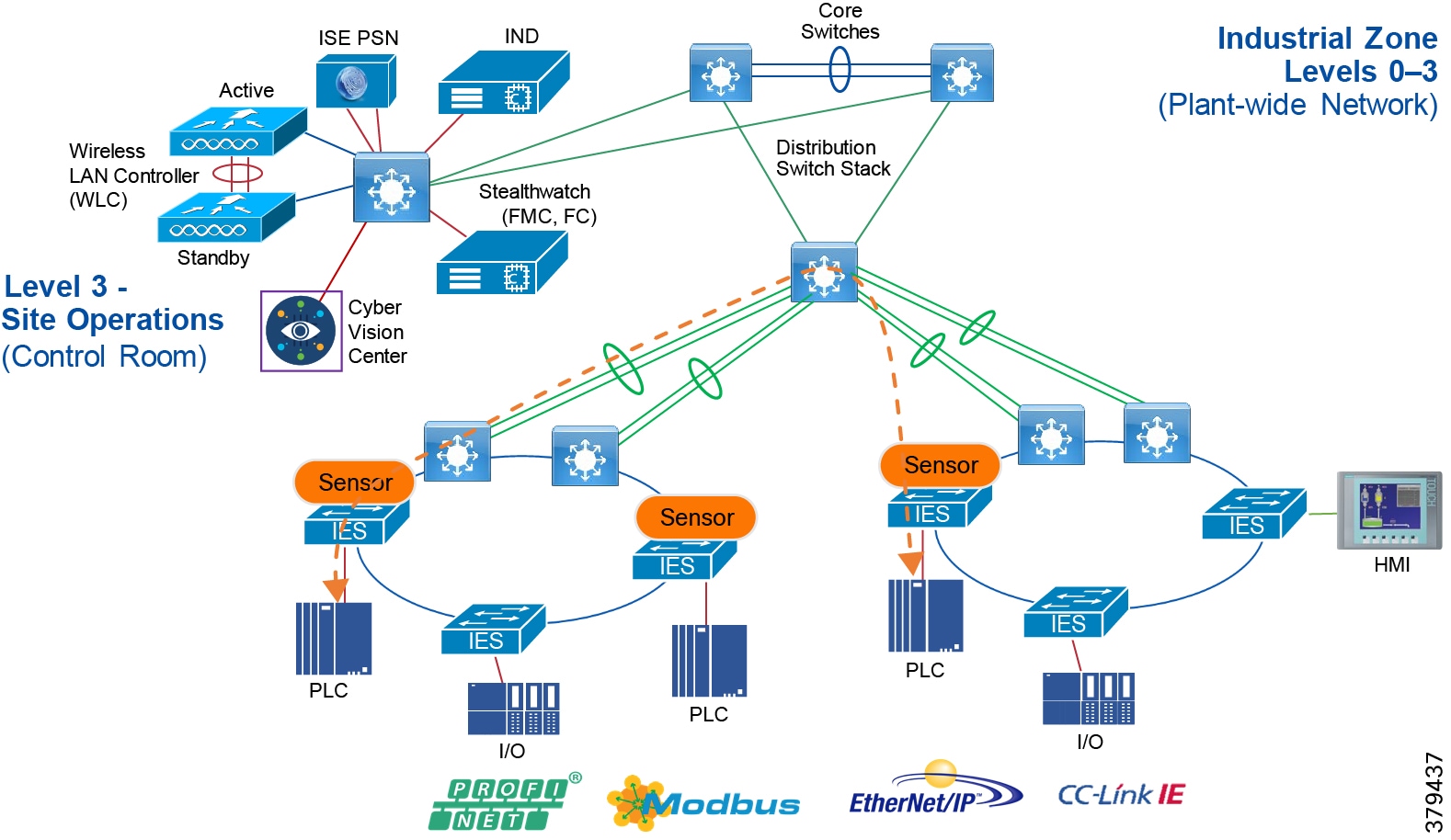
Allowing a server or any other device in Level-3 Site Operation, IDMZ or Enterprise Zone to communicate with an IACS asset in the Cell/Area Zone is called North-South communication. In Figure 62, the Engineering Workstation (EWS) is accessing a controller in the Cell/Area Zone and this communication flow is defined as North-South communication.
Figure 62 North-South Communication in a Plant-wide Network
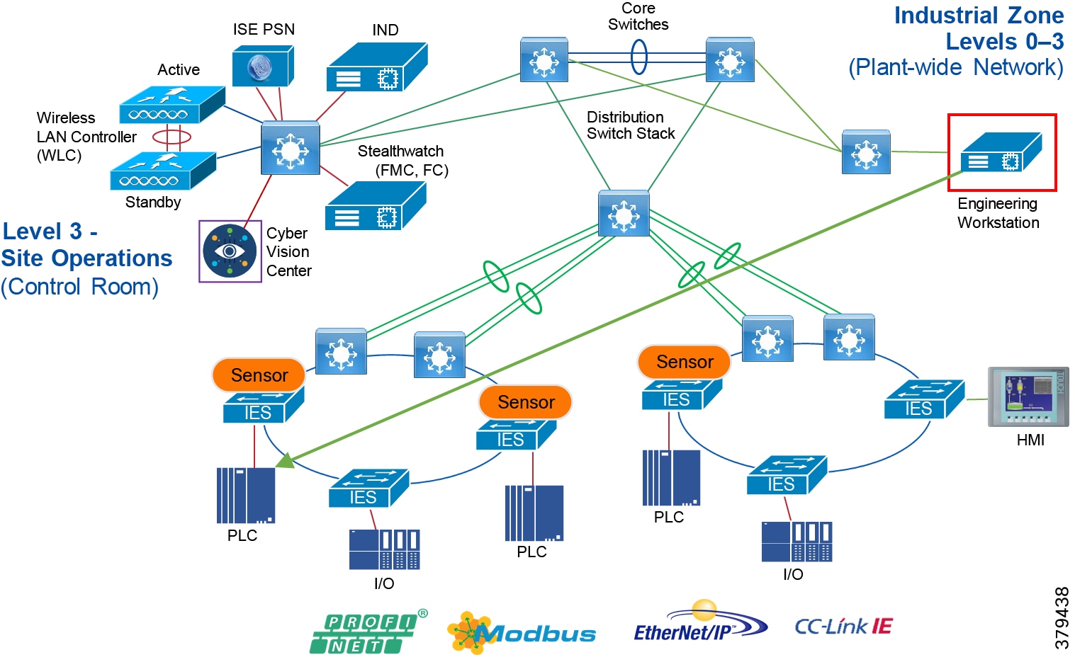
Cell/Area Zone Segmentation
IT security architects in conjunction with a control system engineer should design an access policy that specifies the East-West and North-South communication flows that must be allowed in an IACS network. In an IACS network, having an open policy that allows every IACS asset to communicate with every IACS asset is convenient, but that approach increases the risk of cyber threat propagation. On the other hand, implementing a restrictive policy that does not allow any inter Cell/Area Zone communication is also counterproductive because certain IACS assets need to access other IACS assets that exist in different Cell/Area Zones. Since the exact requirements of a particular scenario are based on the current IACS application requirements, specifying a policy that would work for all the deployments is not possible. Hence in this guide, an access policy example is shown that can be customized for use in different environments.
Assumptions about the access policy for an IACS network:
■![]() All the traffic within the Cell/Area Zone is implicitly permitted because it is assumed that a Cell/Area Zone is formed because a group of IACS assets need to communicate with each other, so no enforcement is applied to any IES in the Cell/Area Zone.
All the traffic within the Cell/Area Zone is implicitly permitted because it is assumed that a Cell/Area Zone is formed because a group of IACS assets need to communicate with each other, so no enforcement is applied to any IES in the Cell/Area Zone.
■![]() All the traffic between any two different Cell/Area Zones will be policed. As an example, in Figure 63 Controller_A in one Cell/Area Zone is allowed to access Controller_C in another Cell/Area Zone, but Controller_B is not allowed to access Controller_C.
All the traffic between any two different Cell/Area Zones will be policed. As an example, in Figure 63 Controller_A in one Cell/Area Zone is allowed to access Controller_C in another Cell/Area Zone, but Controller_B is not allowed to access Controller_C.
The next few subsections describe the general idea of segmentation, the different types of segmentation, and the pros and cons of choosing a segmentation technique.
Figure 63 Example of Enforcement in East-West Traffic Flow
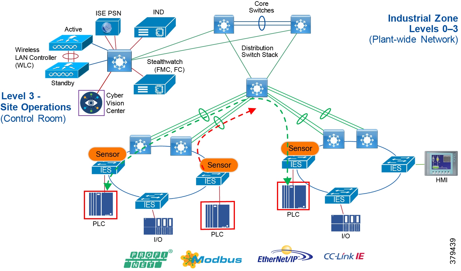
Segmentation Using a Layer 3 Access Control List (ACL)
When an IACS asset is not configured with MAC authentication bypass (MAB) and is unable to get a downloadable access control list (dACL) from ISE, use a static ACL on the distribution switch which is connecting different Cell/Area Zones. In Figure 64, ACL is applied on the distribution switch connecting the two Cell/Area Zones. In Figure 64, the ACL must allow communication between 10.20.25.10 and 10.20.8.10 so that Controller-A is able to establish communication with Controller-B.
Figure 64 Segmentation Using Layer 3 ACL
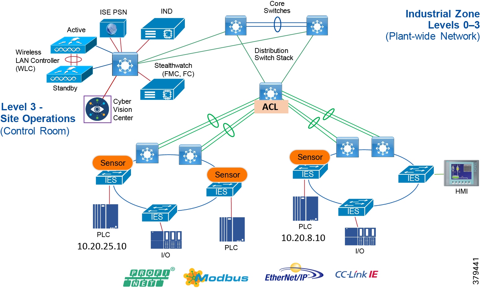
The above method of managing the ACL has similar disadvantages as the dACL. Whenever the controller IP address changes or is moved to a different location, then the ACL needs to be updated. The old entries need to be purged and the new entries added. This process can be burdensome and may lead to an IT security architect making mistakes.
Segmentation Using Downloadable Access Control Lists (dACLs)
Segmentation is the practice of zoning the IACS network to create smaller domains of trust to help protect the IACS network from known and unknown risks in the network. This section describes the first approach to segmentation by using dACLs. See Figure 65, which describes how a dACL is provisioned on a device when an IACS asset gets attached to the network. In Figure 65, there are two Cell/Area Zones connected via a distribution switch. There are two controllers: Controller-A (10.20.25.10) in Cell/Area Zone -1 and Controller-B (10.20.8.10) in Cell/Area Zone -2.
Figure 65 Segmentation Using dACL
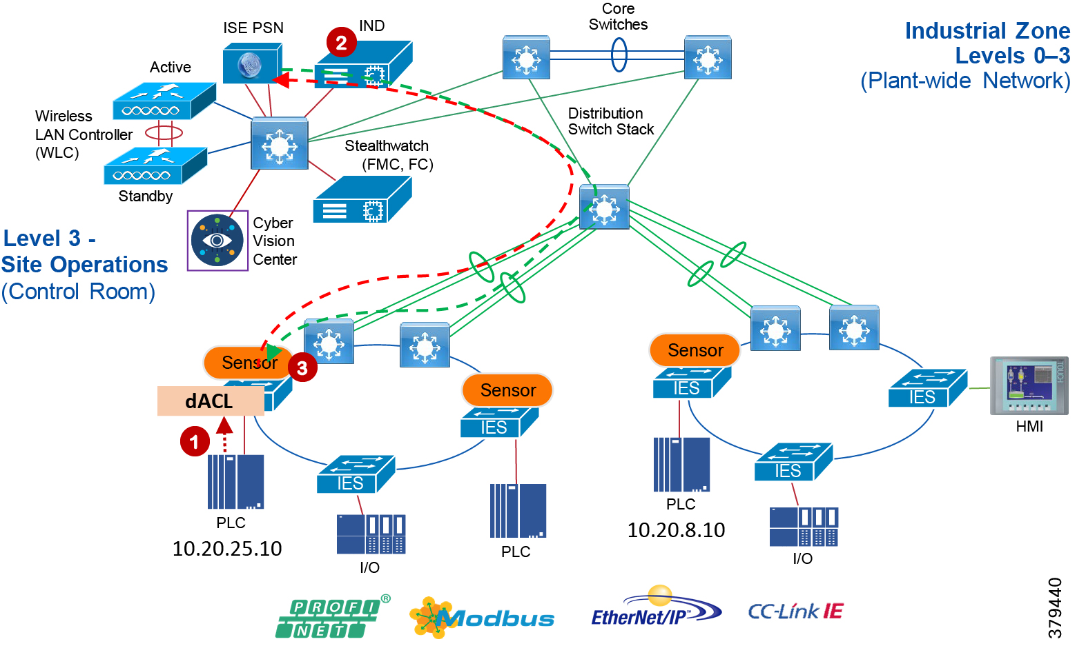
■![]() The Controller connects to an access port on the IES which in turn sends an 802.1X MAB authentication request to the Cisco ISE.
The Controller connects to an access port on the IES which in turn sends an 802.1X MAB authentication request to the Cisco ISE.
■![]() The Cisco ISE, upon receiving the request, processes the request using the configured authentication and authorization policy and sends the authorization result as a dACL to the distribution layer switch.
The Cisco ISE, upon receiving the request, processes the request using the configured authentication and authorization policy and sends the authorization result as a dACL to the distribution layer switch.
■![]() The dACL configured for Controller-A restricts its communication. If a new control needs to be imposed, then add an entry in the dACL.
The dACL configured for Controller-A restricts its communication. If a new control needs to be imposed, then add an entry in the dACL.
The dACL must have Access Control Entries (ACEs) specifying which IP address is allowed to communicate with which IP address. In Figure 65, if CONTROLLER-A with IP address of 10.20.25.10 is permitted to communicate with CONTROLLER-B with IP address of 10.20.8.10, then the ACE must have a permit statement with 10.20.25.10 to 10.20.8.10.
The above method works in controlling access to a Cell/Area Zone and also between the Cell/Area Zones. However, this method has the following disadvantages:
■![]() Assume communication is allowed between CONTROLLER_A and CONTROLLER_B. If CONTROLLER_B moved to a new location with a different IP address, then the dACL needs to be updated.
Assume communication is allowed between CONTROLLER_A and CONTROLLER_B. If CONTROLLER_B moved to a new location with a different IP address, then the dACL needs to be updated.
■![]() If a CONTROLLER_A is allowed to communicate with a particular server in the Industrial Zone and if the IP address of the server changes, then the dACL needs to be updated again.
If a CONTROLLER_A is allowed to communicate with a particular server in the Industrial Zone and if the IP address of the server changes, then the dACL needs to be updated again.
■![]() If there is a large dACL, then it could impact the performance of the distribution switch.
If there is a large dACL, then it could impact the performance of the distribution switch.
Cell/Area Zone Segmentation using TrustSec Technology
Cisco TrustSec technology assigns SGTs to IACS assets, networking devices, and users when they attach to a network. By using these tags, an IT security architect can define an access policy and enforce that policy on any networking device.
Cisco TrustSec is defined in three phases: classification, propagation, and enforcement. When the users and IACS assets connect to a network, the network assigns each entry a specific SGT in a process called classification. Classification can be based on the results of the authentication and authorization policies. For example, an IACS asset can be classified and assigned a specific tag if the IACS asset is a controller, I/O, HMI, or Windows workstation. Depending on the IACS asset type, a separate tag can be assigned to the IACS asset. Figure 66 shows how a controller is assigned an SGT value of 5. The process of SGT assignment is similar to how a dACL is pushed to the Cisco distribution switch when an IACS asset is attached to the IES. The only difference is that instead of a dACL, an SGT value is assigned. As shown in Figure 66, when Controller-A is connected, the switch goes through the 802.1X authentication and authorization with ISE and the result is a tag assignment to the IACS asset.
TrustSec has advantages over static ACLs and dACLs: the ACL methods are difficult to manage, which can introduce errors during the deployment. In addition if the ACL size becomes very large, then this can cause a performance impact on the distribution switch. Finally, both ACL methods require updating with IP address changes.
Figure 66 Cisco TrustSec Device Classification
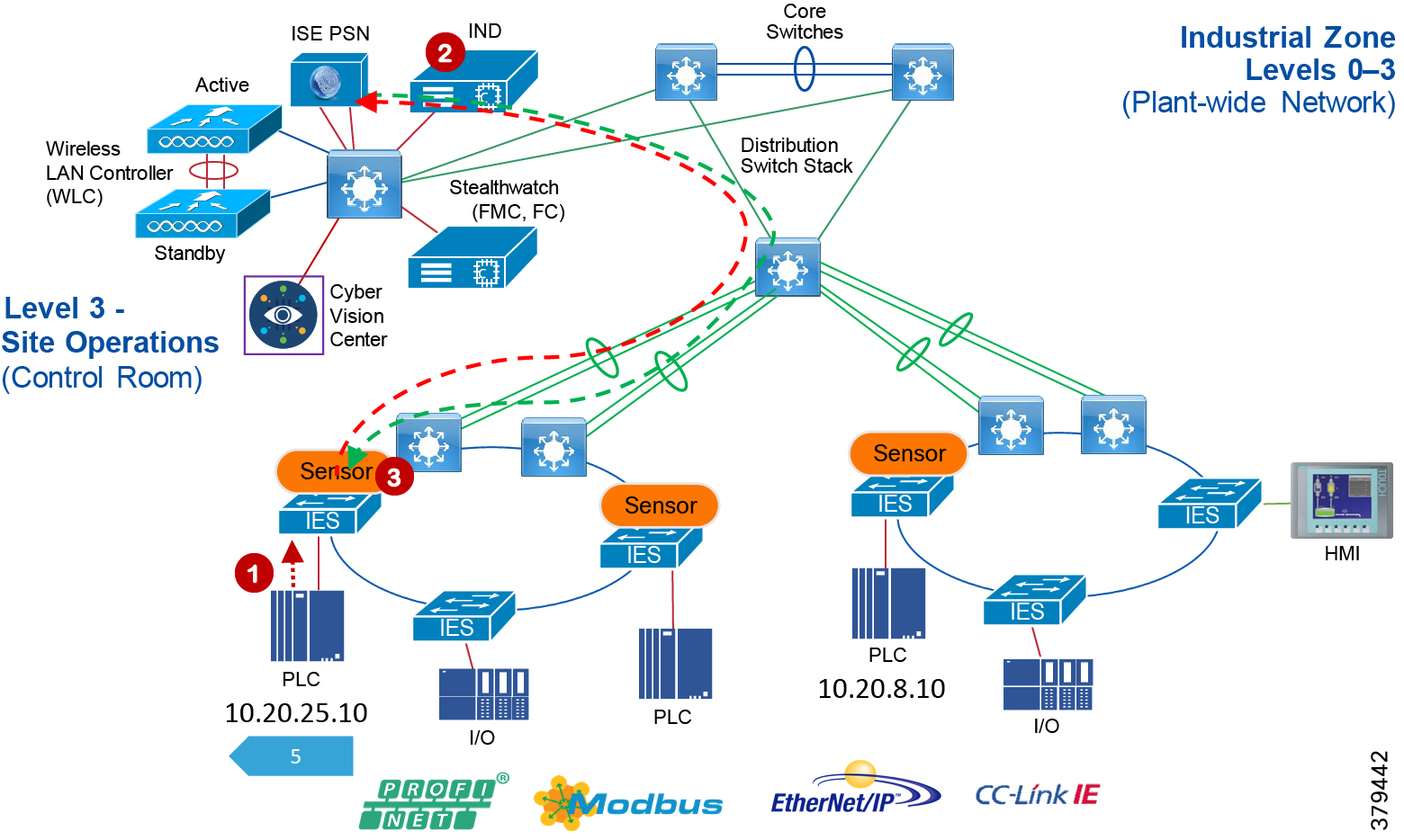
The next phase of TrustSec is propagation, in which the SGT tag on Ethernet frame is sent from one switch or router to another device. The SGT tag that is assigned to the IACS asset must propagate along with every packet generated by the IACS asset. Figure 67 shows how an SGT inserted frame is propagated in the network. In Figure 67, the Controller-A has IP address of 10.20.25.10 and is assigned an SGT value of 5. When an Ethernet frame is generated by Controller-A, the IES inserts the SGT value of 5 along with the IP address and sends it to the next switch. The next switch, if configured with SGT in-line tagging, propagates the same frame to the next switch and this information travels in hop-by-hop fashion to the destination.
Figure 67 Cisco TrustSec SGT Propagation
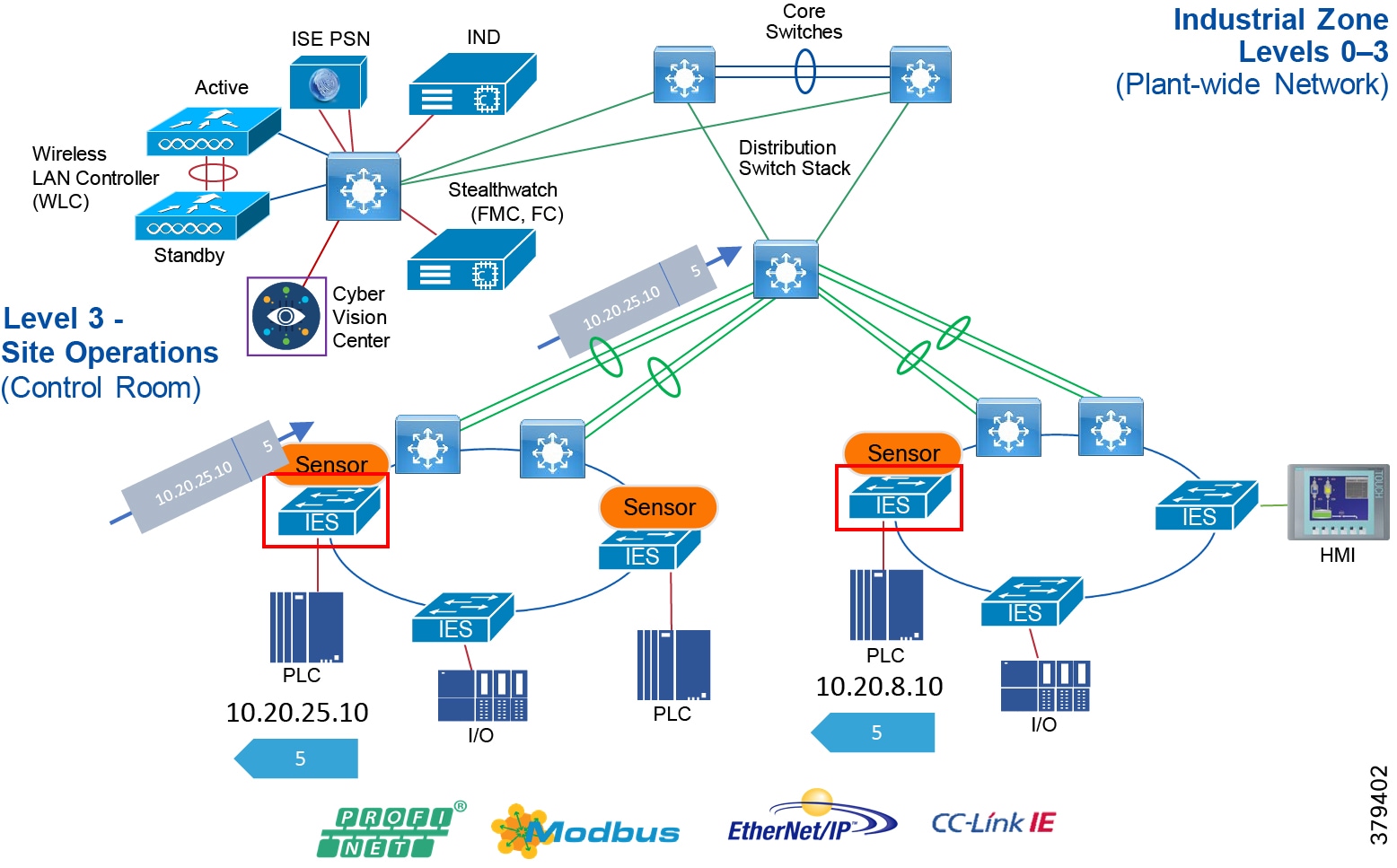
The previous phase describes a scenario for propagation using a method called in-line tagging. However, in certain network topologies, switches in the path from the source to the destination does not support in-line tagging. When that scenario happens, the non-SGT capable switch would ignore the SGT in the frame and would send a normal Ethernet frame on the out-going interface. In other words, for in-line tagging feature to work, all the switches in the path must support this feature.
To circumvent that problem, Cisco TrustSec also supports a different mechanism to transport SGT frames over a path when a non-SGT capable IES (for example, Cisco IE 2000) is present by using SGT Exchange Protocol (SXP). SXP is used to securely share SGT- to-IP address mapping. Figure 68 shows how SGT works. In Figure 68, Controller-A is establishing communication with Controller-B using an SGT tag value of 5. There is a non-SGT device in the path and this switch would ignore the SGT value in the frame coming from the distribution switch. For SGT information to be sent to Switch-B, an SXP tunnel is required between Switch-A and Switch-B. This tunnel would carry the binding information, which is 10.20.25.10 mapped to SGT 5.
Figure 68 Cisco TrustSec SGT Propagation Using SXP Tunnel
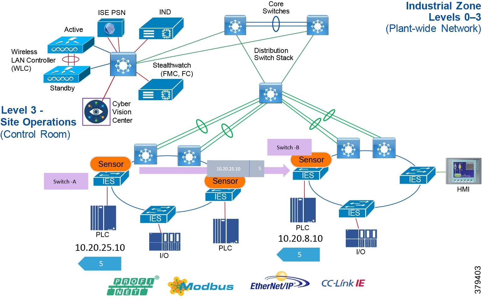
The third stage of Cisco TrustSec is policy enforcement. The enforcement device controls traffic based on the tag information. A TrustSec enforcement point can be a Cisco firewall, router, or switch. The enforcement device takes the source SGT and compares it to the destination SGT to determine if the traffic should be allowed or denied. The advantage of Cisco TrustSec is that any switch, router, or firewall between the source and the destination can impose the policy, but the key requirement is that the enforcement point must be able to map the destination IP address to the tag value. This process is further explained in Figure 69. In this scenario Controller_A has been given SGT value of 5 and Controller_B, which is of similar device type, is also given an SGT value of 5. The I/O device is given a different tag value because it is of a different device type. Now, in this scenario Controller_A is allowed to establish communication with Controller_C. However, the I/O device is not allowed to establish communication with Controller_C. The access policy can be described in Table 33.
| SGT 5 | SGT 6 | |
|---|---|---|
| SGT 5 | Yes | No |
| SGT 6 | No | No |
The next step is to determine where to apply the policy. As shown in Figure 69, the enforcement can be at switches A, B, C, or D. However, as previously indicated, for a switch to enforce a policy it must be able to derive the destination IP address to the tag value. For example, at point A there are two flows occurring: 1) 10.20.25.10, 5 ---- 10.20.8.10, 5 and 2) 10.20.25.12,6 --- 10.20.8.10,5. If the access policy at point A is imposed, then the switch would be only able to understand the source tag, but it has no knowledge of the destination IP address to tag mapping. Switch A would see that the destination IP address is 10.20.8.10, but it does not know that 10.20.8.10 is mapped to tag value of 5, which should be allowed. The same behavior would be seen if the policy is applied at the point B. If the policy is applied at point C or D it would work because both C, which is Layer 2 adjacent to D, and Switch D, which is directly attached to Controller C, would be able to enforce the policy correctly because it would be able to derive the association between the destination IP and the associated SGT value.
Even though applying the access policy at the point which is closest to the IACS asset is the preferred choice, in some situations a policy needs to be applied at a different point. However SGT and IP address mapping is lost beyond the local switch of the IACS. To circumvent that problem, establish SXP tunnels to the IES that has IACS assets attached to it. The details of using SXP for deriving the mapping information are covered below.
Figure 69 Access Policy Enforcement Example
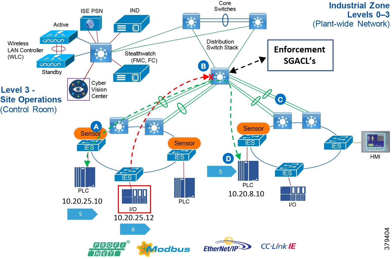
TrustSec Network Policy Enforcement
The IT security architect must next decide where in the design the access policy should be enforced. Policy enforcement occurs at the distribution switch and there are pros and cons associated with each design choice. For example, consider the case where the policy is enforced on an IES located in the Cell/Area Zone. As stated in the previous section, the basic assumption is that every IACS asset in the Cell/Area Zone must be able to access every other IACS asset. The second assumption is that policies are enforced on East-West communication going across the Cell/Area Zones. For example, there are two Cell/Area Zones, Cell/Area Zone-1 and Cell/Area Zone-2, and each Cell/Area Zone contains a PAC and an I/O device. From a Cell/Area Zone-1 intra-zone policy perspective, every PAC and I/O in Cell/Area Zone-1 must be able to access one another. The inter-Cell/Area Zone security access policy is to block the communication between I/O in Cell/Area Zone-1 to the PAC in Cell/Area Zone-2. This security access policy is shown in Table 34.
| PAC-Cell/Area-1 | I/O-Cell/Area-1 | PAC-Cell/Area-2 | I/O-Cell/Area-2 | |
|---|---|---|---|---|
| PAC-Cell/Area-1 | Yes | Yes | No | No |
| I/O-Cell/Area-1 | Yes | Yes | No | No |
| PAC-Cell/Area-2 | No | No | Yes | Yes |
| I/O-Cell/Area-2 | No | No | Yes | Yes |
When designing a security policy using TrustSec, associate each IACS asset with a tag. In the example of a PAC with tag 10 and an I/O device with tag 20, two policy tables are needed: 1) Intra_Cell/Area Zone and 2) Inter_Cell/Area Zone.
| 10 | 20 | |
|---|---|---|
| 10 | Yes | Yes |
| 20 | Yes | Yes |
| 10 | 20 | |
|---|---|---|
| 10 | No | No |
| 20 | No | No |
As seen above, the Cell/Area Zone IES needs to have two tables implemented and that is not possible with the current design. The current TrustSec policy enforcement supports only a single matrix. To ensure both objectives are achieved, implement the security access policy on the distribution switch and do not have any enforcement on the Cell/Area Zone IES. By doing so, the Table 35and Table 36 policy requirements have been met because when no policy is imposed on the Cell/Area Zone IES, then all the IACS assets within the Cell/Area Zone IES can communicate. When Figure 69 is implemented on the distribution switch, then the inter-Cell/Area Zone or East-West communication can be restricted. Figure 70 shows the inter-Cell/Area Zone security access policy enforcement point. If the industrial security access policy requires intra-Cell/Area Zone access control, this CVD recommends IACS application security such as ODVA, Inc. CIP Security.
Figure 70 Enforcement Point in Industrial Automation Network Security
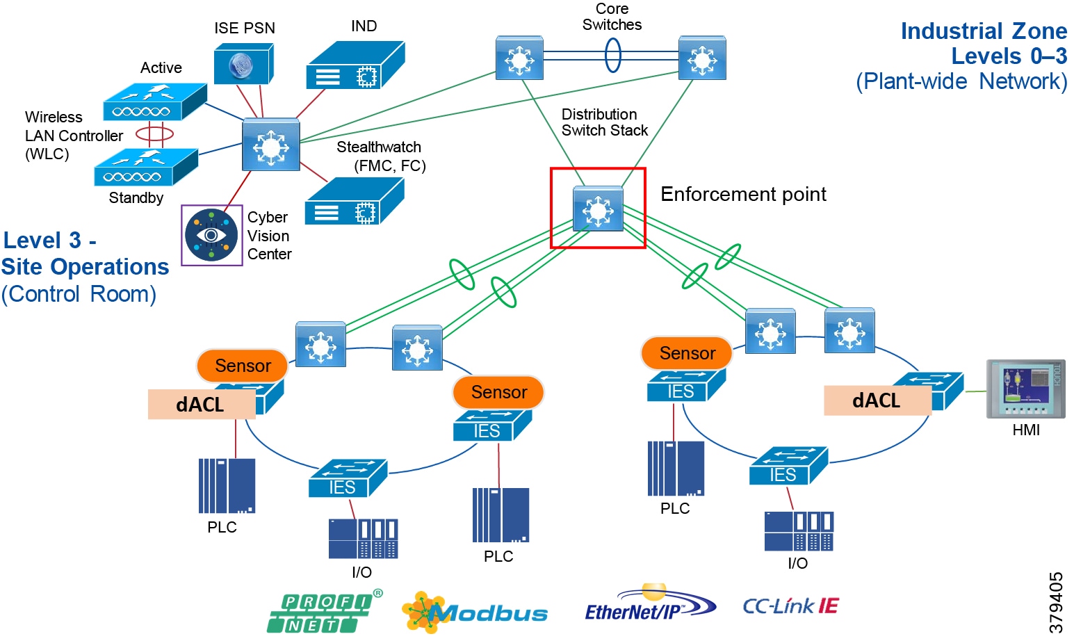
Scalable Group Tag Exchange Protocol Considerations
Scalable Group Tag Exchange Protocol (SXP) is used to propagate the SGTs across network devices that do not have hardware support for TrustSec. SXP is used to transport an endpoint's SGT along with the IP address from one SGT-aware network device to another. The data that SXP transports is called as IP-SGT mapping. The SGT to which an endpoint belongs can be assigned statically or dynamically and the SGT can be used as a classifier in network policies.
SXP uses TCP as its transport protocol to set up an SXP connection between two separate network devices. Each SXP connection has one peer designated as SXP speaker and the other peer as SXP listener. The peers can also be configured in a bi-directional mode where each of them acts as both speaker and listener.
Connections can be initiated by either peer, but mapping information is always propagated from a speaker to a listener.
As shown in the previous section, the enforcement is moved to the distribution switch, so the distribution switch needs to derive the destination IP address to SGT. This is because the Ethernet frame has only the source SGT information and to enforce the policy the distribution switch needs to learn the SGT binding associated with the destination IP address. To help the distribution switch to derive the destination tag, SXP tunnels are needed from the access layer IES to the distribution.
In the current design, SXP tunnels are established from the access layer IES to the Cisco ISE and the distribution switch also has an SXP tunnel to the Cisco ISE. This way the IP-SGT binding information is sent to the Cisco ISE and the distribution switch learns the IP-SGT binding information from the Cisco ISE. Figure 71 depicts the design.
Figure 71 SXP Design in Industrial Automation Network Security CVD
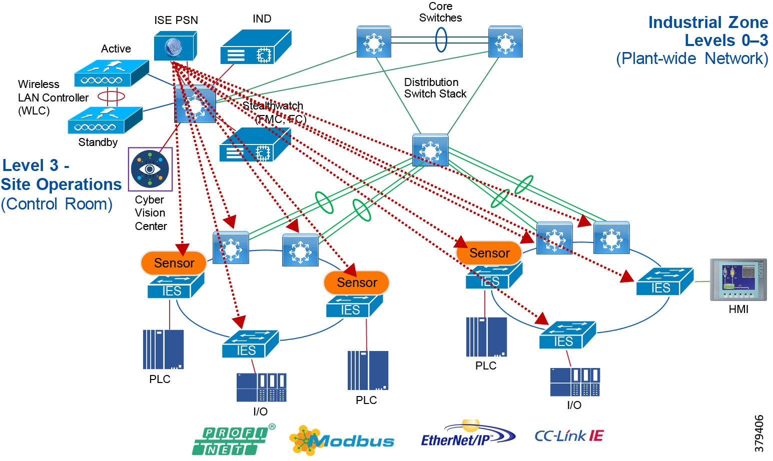
NetFlow
The Cisco IE 3400, Cisco IE 4000, Cisco IE 4010, Cisco IE 5000, Cisco Catalyst 3850, and Cisco Catalyst 9300 support full Flexible NetFlow. NetFlow is an embedded instrumentation within Cisco software to characterize network operation. It provides visibility into the data flows through a switch or router. Enabling NetFlow provides a trace of every data conversation in the network without the need for any SPAN ports.
Figure 72 NetFlow Example
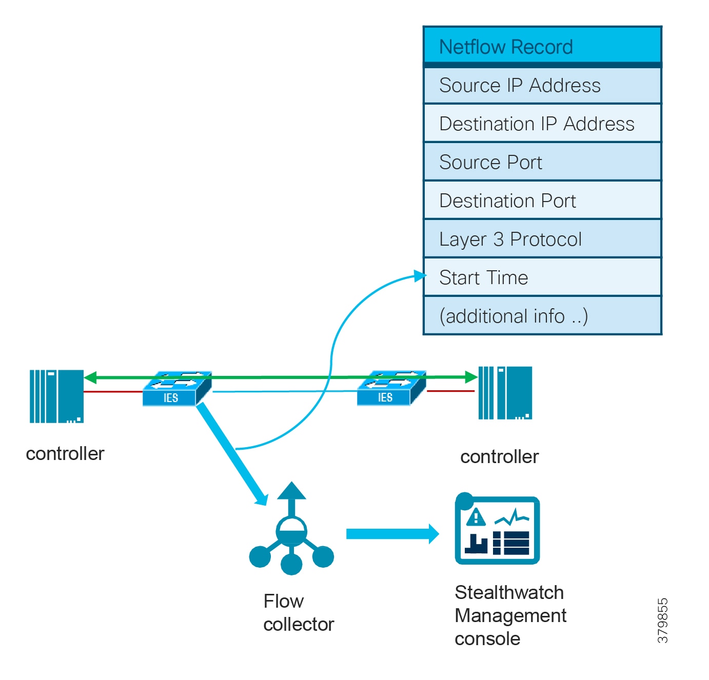
Each packet that is forwarded within a router or switch is examined for a set of IP packet attributes. These attributes are the IP packet identity or fingerprint of the packet and determine if the packet is unique or similar to other packets.
Traditionally, an IP Flow is based on a set of 5 and up to 7 IP packet attributes.
IP packet attributes used by NetFlow:
■![]() IP source address
IP source address
■![]() IP destination address
IP destination address
■![]() Source port
Source port
■![]() Destination port
Destination port
■![]() Layer 3 protocol type
Layer 3 protocol type
■![]() Class of Service
Class of Service
■![]() Router or switch interface
Router or switch interface
All packets with the same source and destination IP address, source and destination ports, protocol interface, and class of service are grouped into a flow and then packets and bytes are tallied and stored in the NetFlow cache. The cache can then be exported to a system such as Cisco Stealthwatch where deeper analysis of the networking data can be used to identify threats or malware. For more information see:
https://www.cisco.com/c/en/us/td/docs/switches/lan/catalyst2960x/software/15-2_5_e/configuration_guide/b_1525
NetFlow Data Collection
A flow is a unidirectional connection between a source and a destination. To describe a full exchange between two devices, two independent unidirectional flows are needed. For example, when data is flowing between client and server, then there are two flows occurring: from client to server and from server to client. NetFlow is a protocol that creates flow records for the packets flowing through the switches and the routers in a network between the end devices and exports the flow records to a flow collector. The data collected by the flow collector is used for different applications to provide further analysis. Initially, NetFlow was used for providing traffic statistics in a network, but later it started gaining traction as a network security tool. In the Industrial Automation Network Security CVD, NetFlow is primarily used for providing security analysis, such as malware detection, network anomalies, and so on. There are many advantages in deploying NetFlow:
■![]() NetFlow can be used for both ingress and egress packets.
NetFlow can be used for both ingress and egress packets.
■![]() Each networking device in a network can be independently enabled with NetFlow.
Each networking device in a network can be independently enabled with NetFlow.
■![]() NetFlow does not see a separate management network to collect the traffic.
NetFlow does not see a separate management network to collect the traffic.
In a normal flow the 5-tuples information (source IP, destination IP, source port, destination port, and protocol) information is recorded as shown in Figure 73.
Figure 73 NetFlow Data Collection
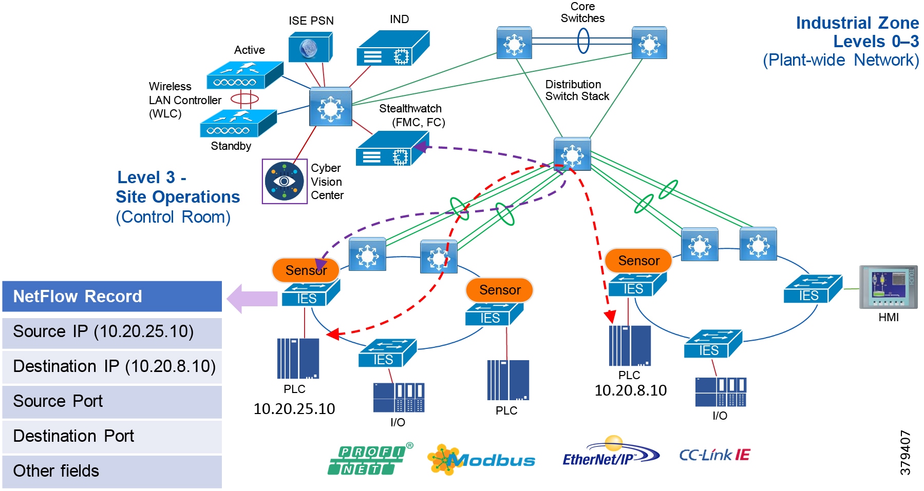
With the latest releases of NetFlow, the switch or router can gather additional information such as ToS, source MAC address, destination MAC address, interface input, interface output, and so on. For Cisco Cyber Vision and ISE integration, collecting the MAC address of the device is very critical. The following configuration shows the information collected at the IES in the Cell/Area Zone:
Configuration of NetFlow records can be done by using IND plug-and-play, which is discussed in more detail in the implementation guide. The next important consideration is on managing flows. As network traffic traverses the Cisco device, flows are continuously created and tracked. As the flows expire, they are exported from the NetFlow cache to the Stealthwatch Flow Collector. A flow is ready for export when it is inactive for a certain time (for example, no new packets are received for the flow) or if the flow is long lived (active) and lasts greater than the active timer (for example, long FTP download and the standard CIP/IO connections). There are timers to determine whether a flow is inactive or a flow is long lived.
After the flow time out the NetFlow record information is sent to the flow collector and deleted on the switch. Since the NetFlow implementation is done mainly to detect security-based incidents rather than traffic analysis, The recommended timeout for the Cisco IE 4000, Cisco IE 4010, Cisco IE 5000, and Cisco Catalyst 9300 switches is 60 seconds for the active timeout and 30 seconds for the inactive timeout. For the Cisco IE 3400, the active is 1800 seconds, the inactive is 60 seconds, and the export timeout is 30 seconds.
The next consideration is on enabling NetFlow in the network. This guide recommends using NetFlow for security, therefore the recommendation is to enable NetFlow monitoring on all the interfaces in the Industrial Automation network.
Stealthwatch Deployment Considerations
The main components of the Steatlthwatch system are:
■![]() Flow Collectors
Flow Collectors
■![]() Stealthwatch Management Console
Stealthwatch Management Console
Note: The respective systems reside on different virtual or hardware appliances.
The Flow Collector collects the NetFlow data from the networking devices, analyzes the data gathered, creates a profile of normal network activity, and generates an alert for any behavior that falls outside of the normal profile. Based on the network flow traffic, there could be one or multiple Flow Collectors in a network. The Stealthwatch Management Console (SMC) provides a single interface for the IT security architect to get a contextual view of the entire network traffic.
The SMC has a Java-based thick client and a web interface for viewing data and configurations. The SMC enables the following:
■![]() Centralized management, configuration, and reporting for up to 25 Flow Collectors
Centralized management, configuration, and reporting for up to 25 Flow Collectors
■![]() Graphical Charts for visualizing traffic
Graphical Charts for visualizing traffic
■![]() Drill down analysis for troubleshooting
Drill down analysis for troubleshooting
■![]() Consolidated and customizable reports:
Consolidated and customizable reports:
–![]() Trend analysis
Trend analysis
–![]() Performance monitoring
Performance monitoring
–![]() Immediate notification of security breaches
Immediate notification of security breaches
Some important considerations when deploying a Steathwatch system include:
■![]() Stealthwatch is available as both hardware (physical appliances) and virtual appliances. To install hardware and software appliances, refer to the Stealthwatch guide:
Stealthwatch is available as both hardware (physical appliances) and virtual appliances. To install hardware and software appliances, refer to the Stealthwatch guide:
https://www.cisco.com/c/dam/en/us/td/docs/security/stealthwatch/system_installation_configuration/SW_7_0_Installation_and_Configuration_Guide_DV_1_0.pdf
■![]() The resources allocation for the Stealthwatch Flow Collector are dependent on the number of flows per second expected on the network and the number of exporters (networking devices that are enabled with NetFlow) and the number of hosts attached to the each networking device. The scalability requirements for the Flow Collector are available at:
The resources allocation for the Stealthwatch Flow Collector are dependent on the number of flows per second expected on the network and the number of exporters (networking devices that are enabled with NetFlow) and the number of hosts attached to the each networking device. The scalability requirements for the Flow Collector are available at:
https://www.cisco.com/c/dam/en/us/td/docs/security/stealthwatch/system_installation_configuration/SW_7_0_Installation_and_Configuration_Guide_DV_1_0.pdf
■![]() The data storage requirements must be taken into consideration, which are again dependent on the number of flows in the network. The sizing table for data storage is available at:
The data storage requirements must be taken into consideration, which are again dependent on the number of flows in the network. The sizing table for data storage is available at:
https://www.cisco.com/c/dam/en/us/td/docs/security/stealthwatch/system_installation_configuration/SW_7_0_Installation_and_Configuration_Guide_DV_1_0.pdf
■![]() A specific set of ports needs to be open for the Stealthwatch solution in both the inbound and outbound directions. For the complete list of ports that are recommended to be open, refer to:
A specific set of ports needs to be open for the Stealthwatch solution in both the inbound and outbound directions. For the complete list of ports that are recommended to be open, refer to:
https://www.cisco.com/c/dam/en/us/td/docs/security/stealthwatch/system_installation_configuration/SW_7_0_Installation_and_Configuration_Guide_DV_1_0.pdf
Cisco ISE Deployment Considerations
Deploying Cisco ISE in a large network requires an IT security architect to consider several factors such as scalability and high-availability. This design guide covers many factors related to deploying a large-scale Cisco ISE deployment. We encourage the reader to read the CPwE DIG to develop a good understanding of large-scale solution deployments. Some of the key recommendations given in the design guide are shown here as a quick reference.
In the distributed installation, the Cisco ISE system is divided into three discrete nodes (personas)-Administration, Policy Service, and Monitoring-which are described as follows:
■![]() The Policy Administration Node (PAN) allows the Enterprise IT team to perform all administrative operations on the distributed Cisco ISE system. The PAN (located in the Enterprise Zone) handles all system configurations that are related to functionality such as authentication and authorization policies. A distributed Cisco ISE deployment can have one or a maximum of two nodes with the Administration persona that can take on the primary or secondary role for high availability.
The Policy Administration Node (PAN) allows the Enterprise IT team to perform all administrative operations on the distributed Cisco ISE system. The PAN (located in the Enterprise Zone) handles all system configurations that are related to functionality such as authentication and authorization policies. A distributed Cisco ISE deployment can have one or a maximum of two nodes with the Administration persona that can take on the primary or secondary role for high availability.
■![]() The Policy Service Node (PSN) provides client authentication, authorization, provisioning, profiling, and posturing services. The PSN (located within the Industrial and the Enterprise Zone) evaluates the policies and provides network access to devices based on the result of the policy evaluation. At least one node in a distributed setup should assume the Policy Service persona and usually more than one PSN exists in a large distributed deployment.
The Policy Service Node (PSN) provides client authentication, authorization, provisioning, profiling, and posturing services. The PSN (located within the Industrial and the Enterprise Zone) evaluates the policies and provides network access to devices based on the result of the policy evaluation. At least one node in a distributed setup should assume the Policy Service persona and usually more than one PSN exists in a large distributed deployment.
■![]() The Monitoring Node (MnT) functions as the log collector and stores log messages and statistics from all the PAN and PSN devices in a network. The MnT (located in the Enterprise Zone) aggregates and correlates the data in meaningful reports for the IT and OT personnel. A distributed system can have at least one or a maximum of two nodes with the Monitoring persona that can take on primary or secondary roles for high availability.
The Monitoring Node (MnT) functions as the log collector and stores log messages and statistics from all the PAN and PSN devices in a network. The MnT (located in the Enterprise Zone) aggregates and correlates the data in meaningful reports for the IT and OT personnel. A distributed system can have at least one or a maximum of two nodes with the Monitoring persona that can take on primary or secondary roles for high availability.
For optimal performance and resiliency, this CVD provides these recommendations for the Industrial Automation Identity and Mobility Services architecture:
■![]() Administration and Policy Service personas should be configured on different Cisco ISE nodes.
Administration and Policy Service personas should be configured on different Cisco ISE nodes.
■![]() Monitoring and Policy Service personas should not be enabled on the same Cisco ISE node. The Monitoring node should be dedicated solely to monitoring for optimum performance.
Monitoring and Policy Service personas should not be enabled on the same Cisco ISE node. The Monitoring node should be dedicated solely to monitoring for optimum performance.
■![]() A PSN should be placed in the Industrial Zone (Levels 0-3) to provide services for clients in the Industrial Zone. If the Enterprise and Industrial Zones become isolated, any existing clients will still be able to securely access the network. For best practices, see Previous and Related Documentation for links to the Industrial Automation IDMZ CVD DIG.
A PSN should be placed in the Industrial Zone (Levels 0-3) to provide services for clients in the Industrial Zone. If the Enterprise and Industrial Zones become isolated, any existing clients will still be able to securely access the network. For best practices, see Previous and Related Documentation for links to the Industrial Automation IDMZ CVD DIG.
■![]() A PSN should also be present in the Enterprise Zone to authenticate corporate mobile users who connect to the corporate network through the IDMZ in a secure data tunnel. This scenario is covered in detail later in the document.
A PSN should also be present in the Enterprise Zone to authenticate corporate mobile users who connect to the corporate network through the IDMZ in a secure data tunnel. This scenario is covered in detail later in the document.
Based on the recommendations above, a typical distributed Cisco ISE deployment in the Industrial Automation architecture consists of the following nodes (hardware appliances or VMs) as shown in Figure 74.
■![]() One Primary Administration/Secondary Monitoring node
One Primary Administration/Secondary Monitoring node
■![]() One Secondary Administration/Primary Monitoring node
One Secondary Administration/Primary Monitoring node
■![]() One or several PSN in the Enterprise Zone
One or several PSN in the Enterprise Zone
■![]() One or several PSN in the Industrial Zone
One or several PSN in the Industrial Zone
Note: The number of PSN in the Enterprise and Industrial Zones may depend on the company size, the number of active clients, redundancy requirements, and geographical distribution (for example, one PSN per each plant).
Figure 74 ISE Deployment Models
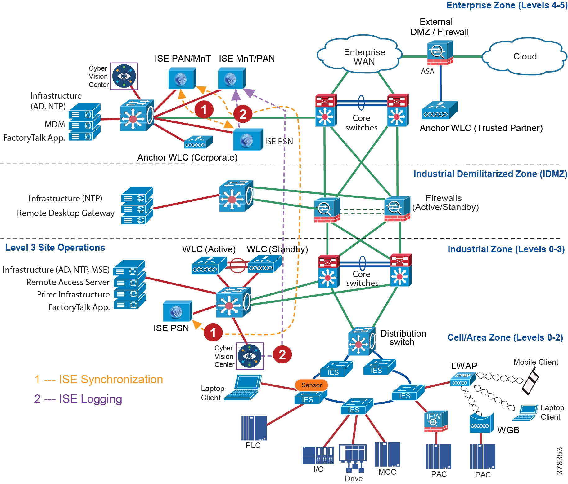
IPDT Considerations
IP Device Tracking (IPDT) is a feature that allows an IES or any other switch or router to keep track of connected hosts attached to it. The IPDT feature must be enabled for several security features such as dot1x,
MAB, Web-Auth, auth-proxy, and so on. The IPDT feature keeps mappings between IP addresses and MAC addresses. To do the tracking, the IES sends an ARP probe with default interval of 30 seconds. The probes are implemented as per RFC5227 where the source IP address is set to 0.0.0.0. If the IPDT feature is enabled with a default source IP address of 0.0.0.0, then there could be conflict between the IES and an IACS asset that is also doing device tracking (the duplicate IP address 0.0.0.0) problem is explained in:
https://www.cisco.com/c/en/us/support/docs/ios-nx-os-software/8021x/116529-problemsolution-product-00.html).
The recommended option is to modify the standard IP address used with the IPDT feature prior to the implementation of IPDT. The following command can be used on an IES:
This command uses the source of the probe to SVI if present and falls back to 169.254.26.64, which is a link-local IP address. The rationale for using a link-local IP address as a fallback is based on the assumption that any device attached to the switch does not have a link-local IP address. The link-local IP address is used only to route packets within a local segment and if a router receives a link-local IP address then it does not forward the packet. The IT security architect must verify if there is any link-local IP address present in the network before enabling the command.
Note: IPDT, which operates in accordance with RFC 5227, must be enabled on the IES to implement RADIUS, downloadable ACL, and SGTs. IPDT uses ARP probes to determine the IP addresses of hosts on different ports; this behavior may disrupt IACS assets devices and applications.
IPDT should only be enabled in the following situations on IES ports with 802.1X authentication:
■![]() Maintenance ports and/or designated non-IACS equipment ports
Maintenance ports and/or designated non-IACS equipment ports
■![]() IACS ports with MAC Authentication Bypass if DACL is required by the security policy, with proper IPDT workaround applied and tested with IACS assets devices and applications
IACS ports with MAC Authentication Bypass if DACL is required by the security policy, with proper IPDT workaround applied and tested with IACS assets devices and applications
By default, IPDT should not be enabled on ports connected to IACS assets devices and applications if DACL functionality is not required. For more information and IPDT workarounds see:
https://www.cisco.com/c/en/us/td/docs/solutions/Verticals/CPwE/5-0/Firewalls/DIG/CPwE-5-IFS-DIG.html
OT Intent-based Security for Industrial Automation Use Cases
This section describes the implementation of the network security use cases documented in this guide. The objective is to provide more details about each of the following use cases and also how different components, such as IES, ISE, Cisco Cyber Vision, and Stealthwatch work together to support these use cases. This section describes the following use cases:
■![]() Visibility and Identification of network devices and IACS assets in the Cell/Area Zone
Visibility and Identification of network devices and IACS assets in the Cell/Area Zone
■![]() Group policy assignment of IACS assets in Industrial Zone
Group policy assignment of IACS assets in Industrial Zone
■![]() Malware detection with NetFlow in the Cell/Area Zone and Level-3 Site Operations zones
Malware detection with NetFlow in the Cell/Area Zone and Level-3 Site Operations zones
■![]() OT-managed remote user (employee or partner) access to the plant infrastructure
OT-managed remote user (employee or partner) access to the plant infrastructure
■![]() Detection of operational events (enabled by Cisco Cyber Vision)
Detection of operational events (enabled by Cisco Cyber Vision)
Visibility and Identification of IACS Assets in the Cell/Area Zone
The purpose of this use case is to show how an OT control system engineer and IT security architect can work together to gain visibility of the network devices and IACS assets in the Cell/Area Zone. The visibility must be granular enough that the IT security architect can know the type of the IACS asset-Controller, I/O, drive, HMI, and others. To segment traffic flows going across in East-West or North-South direction it is important that the IT security architect gain visibility of the current network topology in the plant-wide network.
Figure 75 illustrates the high-level steps to perform this use case.
Figure 75 Visibility of IACS Assets in the Cell/Area Zone using Cisco Cyber Vision
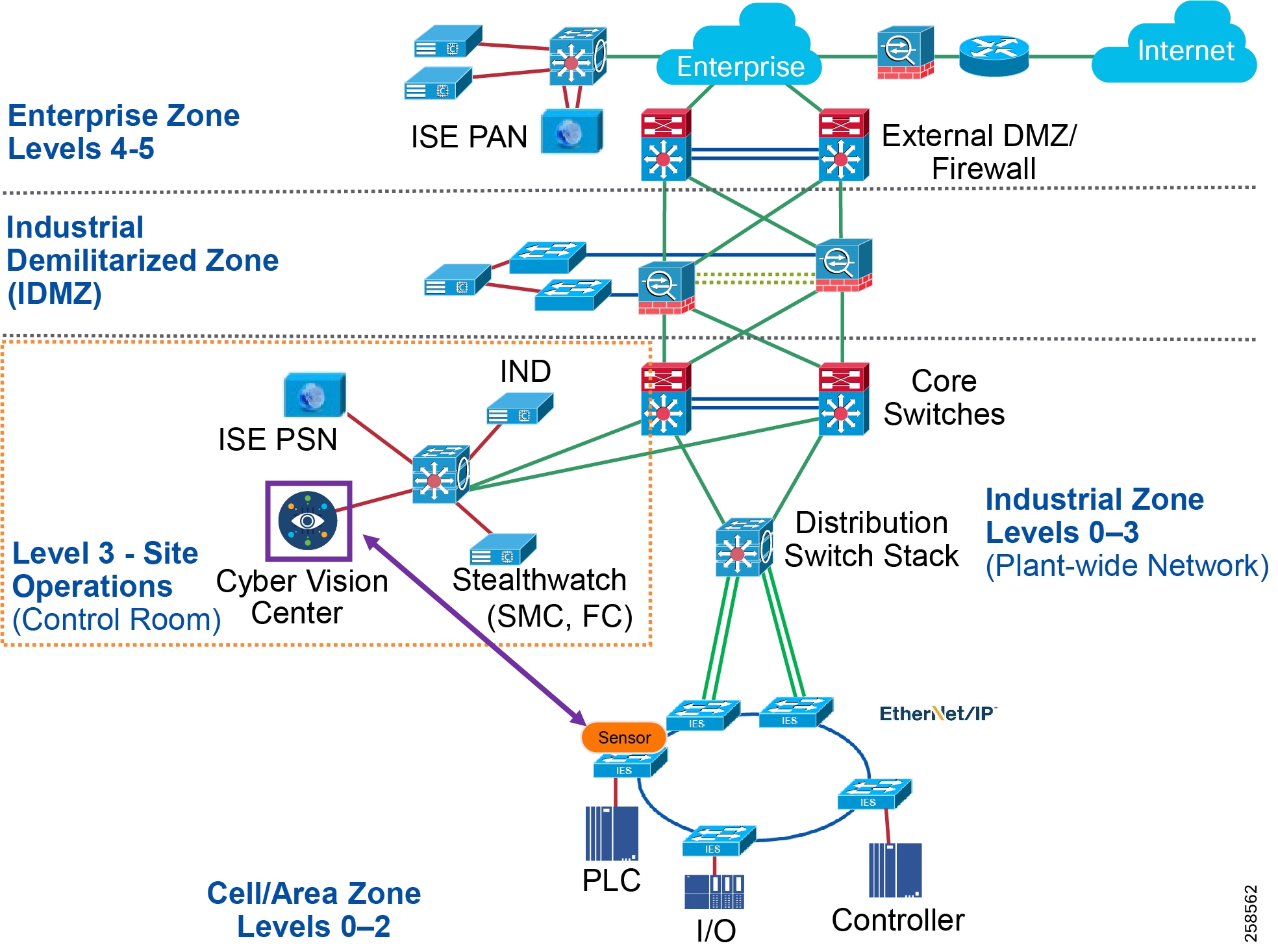
1. ![]() An OT control system engineer decides which IACS assets to monitor, choses Cyber Vision Deployment option, and configures passive monitoring (SPAN) on the ports. Refer to the implementation guide.
An OT control system engineer decides which IACS assets to monitor, choses Cyber Vision Deployment option, and configures passive monitoring (SPAN) on the ports. Refer to the implementation guide.
2. ![]() Cisco Cyber Vision Center dynamically learns the IACS vendor-name, model-name, serial-number, IP-address, mac-address, firmware version, device-name, and other pertinent information. Refer to the implementation guide.
Cisco Cyber Vision Center dynamically learns the IACS vendor-name, model-name, serial-number, IP-address, mac-address, firmware version, device-name, and other pertinent information. Refer to the implementation guide.
Cell/Area Zone Segmentation of IACS Assets using Cisco Cyber Vision
This use case describes in detail how to achieve segmentation of different traffic flows in a Cell/Area Zone using Cisco ISE and Cyber Vision. To understand traffic flows, refer to IACS Traffic Flows in a Network. The idea behind segmentation is defined in Cell/Area Zone Segmentation. This use case describes in detail how to achieve segmentation of different traffic flows in a Cell/Area Zone using Cisco ISE and Cyber Vision.
Segmentation Using Cisco Cyber Vision
Figure 76 Cell/Area Zone Segmentation Using Cisco Cyber Vision
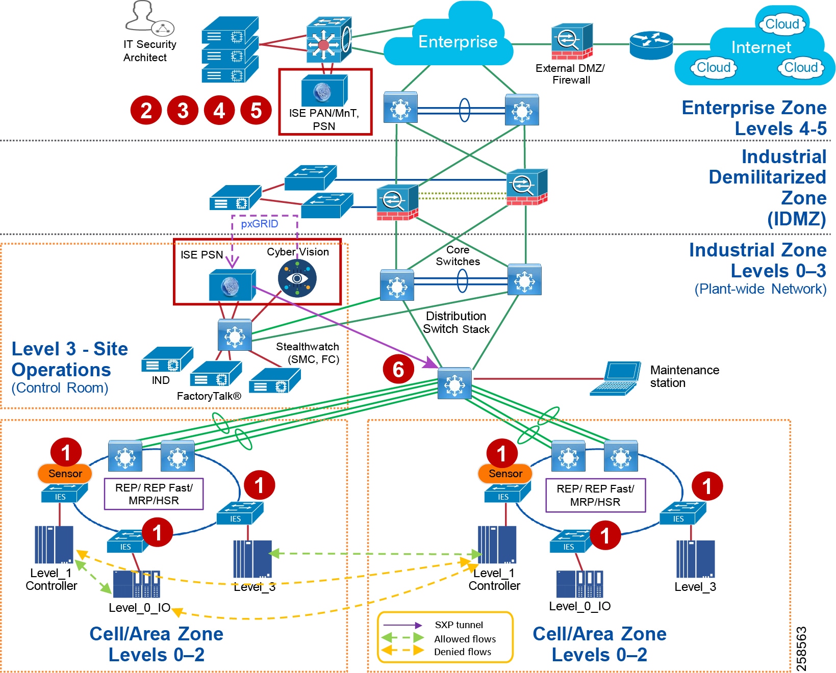
1. ![]() The IT security architect must configure port-based authentication on all the IES. Refer to the implementation guide.
The IT security architect must configure port-based authentication on all the IES. Refer to the implementation guide.
2. ![]() The IT security architect must configure TrustSec SGTs for different IACS assets—Level_1_Controller, Level_0_IO, and Level_3 in ISE. Refer to the implementation guide.
The IT security architect must configure TrustSec SGTs for different IACS assets—Level_1_Controller, Level_0_IO, and Level_3 in ISE. Refer to the implementation guide.
3. ![]() The IT security architect must configure Authentication and Authorization policy in ISE. Refer to the implementation guide.
The IT security architect must configure Authentication and Authorization policy in ISE. Refer to the implementation guide.
4. ![]() The IT security architect must configure SXP tunnels from IES and the distribution switch to ISE. Refer to the implementation guide.
The IT security architect must configure SXP tunnels from IES and the distribution switch to ISE. Refer to the implementation guide.
5. ![]() The IT security architect must configure the TrustSec Policy Matrix on ISE. Refer to the implementation guide.
The IT security architect must configure the TrustSec Policy Matrix on ISE. Refer to the implementation guide.
6. ![]() The IT security architect must configure the enforcement on the Cisco Catalyst 3850, Cisco Catalyst 9300, or Cisco IE 5000 distribution switch. Refer to the implementation guide.
The IT security architect must configure the enforcement on the Cisco Catalyst 3850, Cisco Catalyst 9300, or Cisco IE 5000 distribution switch. Refer to the implementation guide.
Flow-Based Anomaly Detection
This use case describes how an IT security architect can use Stealthwatch along with NetFlow enabled on IES and Cisco Catalyst 3850, Cisco Catalyst 9300, and Cisco Catalyst 9500 acting as distribution switches to monitor the network flows in the plant-wide network. In addition, this use case also shows the integration between the Cisco Cyber Vision and Stealthwatch. The integration between the Cisco Cyber Vision and Stealthwatch helps an IT security architect to understand the context of OT flows happening in the Cell/Area Zone. The integration between Cisco Cyber Vision and Stealthwatch happens by implementing the following steps.
To detect traffic flows occurring in a plant-wide network, it is important that NetFlow is enabled on all the networking devices to capture the traffic flows that are sent to FlowCollector. SMC retrieves the flow data from the FlowCollector and runs pre-built algorithms to display the network flows and also detect and warn if there is any malicious or abnormal behavior occurring in the network. In this guide, three flows are shown to demonstrate the capability of Stealthwatch using NetFlow:
■![]() Traffic between IACS assets in a Cell/Area Zone (Intra-Cell/Area Zone).
Traffic between IACS assets in a Cell/Area Zone (Intra-Cell/Area Zone).
■![]() Traffic between Level_3 IACS assets across the Cell/Area Zone (East-West or Inter-Cell/Area Zone traffic).
Traffic between Level_3 IACS assets across the Cell/Area Zone (East-West or Inter-Cell/Area Zone traffic).
■![]() Traffic between the EWS and a Level_3 IACS asset (North-South) traffic.
Traffic between the EWS and a Level_3 IACS asset (North-South) traffic.
The following steps must be performed by the IT security architect to detect the above-mentioned flows:
1. ![]() IT security architect must enable NetFlow on all the IES and the Cisco Catalyst 3850 switches. Refer to the implementation guide.
IT security architect must enable NetFlow on all the IES and the Cisco Catalyst 3850 switches. Refer to the implementation guide.
2. ![]() The IT Security Architect deploys the Cisco Cyber Vision python scripts in a server.
The IT Security Architect deploys the Cisco Cyber Vision python scripts in a server.
3. ![]() The IT Security Architect using the python script connects to the Cisco Cyber Vision Center and download the host group information.
The IT Security Architect using the python script connects to the Cisco Cyber Vision Center and download the host group information.
4. ![]() The IT Security Architect using the python script connects to the Stealtwatch management console (SMC) and publishes the host group information.
The IT Security Architect using the python script connects to the Stealtwatch management console (SMC) and publishes the host group information.
Figure 77 Flow-Based Anomaly Detection
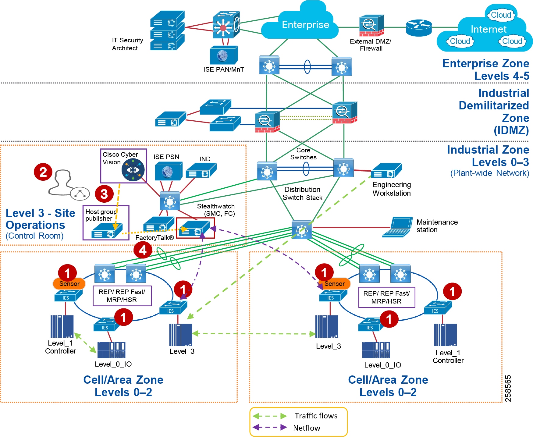
Detection of Malware in Cell/Area Zone and Level-3 Operations
This section discusses how Stealthwatch detects malicious traffic traversing a plant network. When malware is spreading in the network, it becomes very difficult to pinpoint where the malware propagation is occurring. An IT security architect needs to identify the source and then develop a remediation plan to address the problem. Stealthwatch has many inbuilt machine learning algorithms that can assist an IT security professional in detecting possible malware propagation in the network. It can detect abnormal behavior and provide the IP address of the device that is causing the propagation. This information greatly simplifies the detection process.
Without Stealthwatch, IT security architect may have to follow a number of potentially time-consuming steps to investigate the malicious activity, such as shutting down parts of the network and going through logs of many devices. These steps not only take time to isolate, but also increase the risk of other vulnerable devices becoming infected. When active malware is detected, quickly enacting a remediation plan is essential in building a defense against malware.
Often the malware behavior is to immediately scan the network to identify any other vulnerable devices in the plant-wide network. In this CVD, two traffic flows related to malware are discussed:
■![]() An infected laptop attached to an IES. Figure 78 shows an example of how a scan can be performed by an infected laptop.
An infected laptop attached to an IES. Figure 78 shows an example of how a scan can be performed by an infected laptop.
Figure 78 Scan by an Infected Laptop
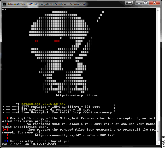
■![]() An infected laptop attached to a Layer-3 site operations center.
An infected laptop attached to a Layer-3 site operations center.
In both the cases, the infected laptop attempts to scan the entire IP address range to identify the next possible targets and attempt to infect them. Stealthwatch would immediately detect a possible infiltration by generating an alarm under High Concern Index. Any alarm that comes under High Concern Index must be immediately taken into consideration and as more malicious behavior is detected with alarms, a host's High Concern Index increments to signify the increasing threat. Figure 79 shows how an alarm is displayed in the SMC. In Figure 79, the host 10.20.25.221 is attempting to do a scan for the 10.17.10.0/24 network.
Figure 79 Alarm Displayed in Stealthwatch Management Console
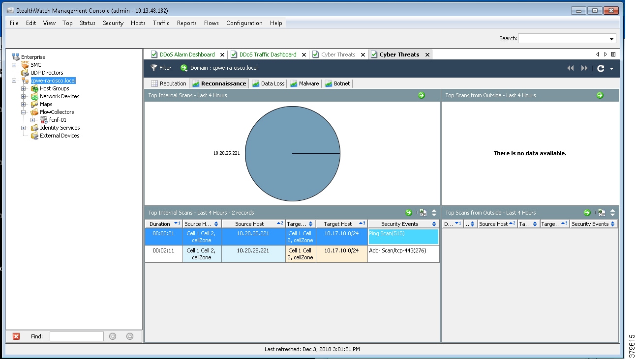
For more information about alarms see:
https://www.cisco.com/c/dam/en/us/td/docs/security/stealthwatch/management_console/smc_users_guide/SW_6_9_0_SMC_Users_Guide_DV_1_2.pdf
Figure 80 shows the scenario where an infected laptop is connected to Cell/Area Zone or Level_3 Site Operations zone and is being detected by Stealthwatch. The steps involved are:
1. ![]() The IES in the Cell/Area Zone or the distribution switch in Level_3 Site Operations is enabled with NetFlow. Refer to the implementation guide.
The IES in the Cell/Area Zone or the distribution switch in Level_3 Site Operations is enabled with NetFlow. Refer to the implementation guide.
2. ![]() The SMC reports an alarm indicating that there is a malicious activity occurring in the network.
The SMC reports an alarm indicating that there is a malicious activity occurring in the network.
3. ![]() An IT security architect responds to the alarm by planning the next stage of remediation that can involve doing further investigation, restricting the access of the IACS asset, and so on.
An IT security architect responds to the alarm by planning the next stage of remediation that can involve doing further investigation, restricting the access of the IACS asset, and so on.
Figure 80 Detection of Malware in the Cell/Area Zone
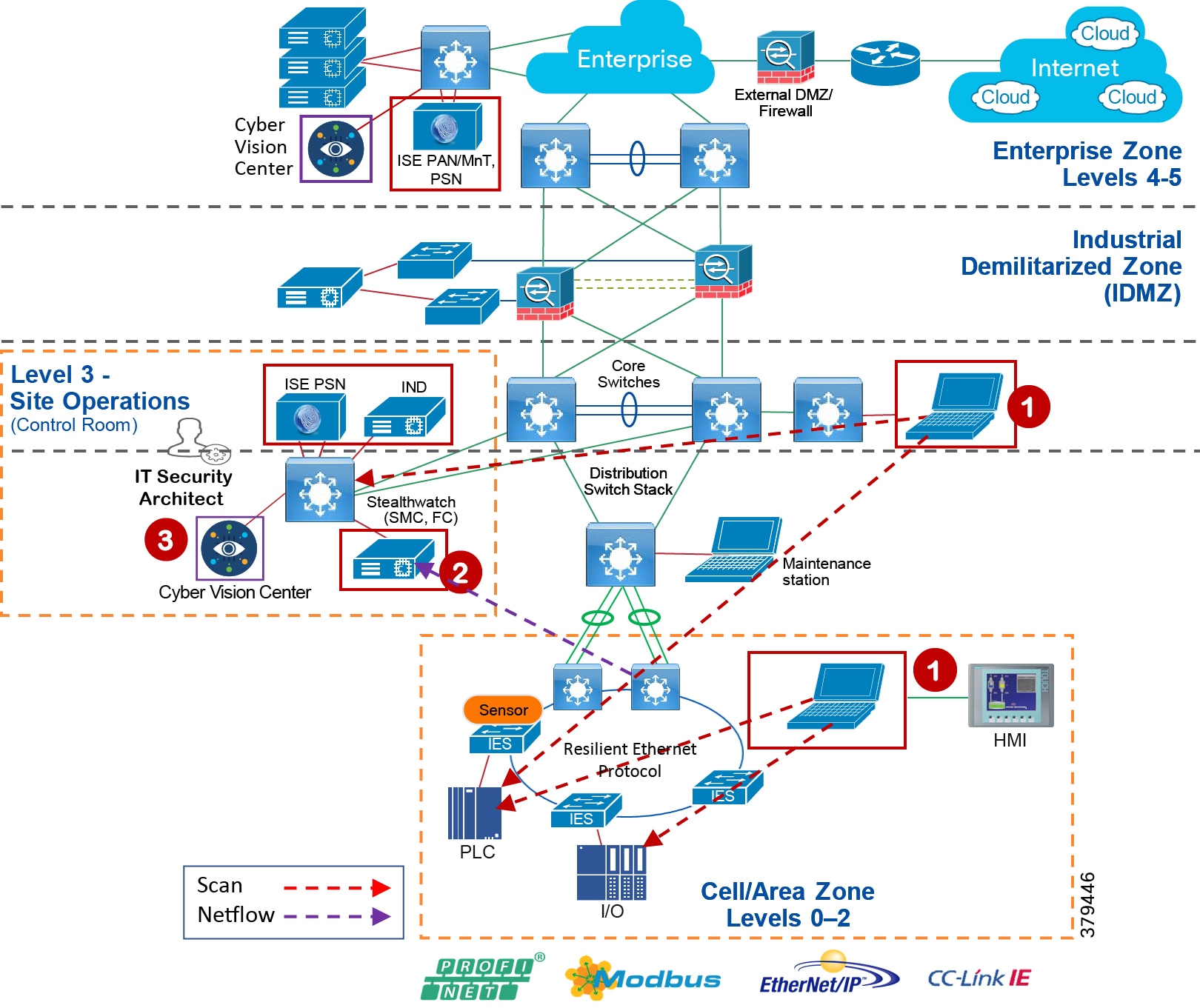
Detection of Operational Events—Enabled by Cisco Cyber Vision
The purpose of this use case is to show how Cisco Cyber Vision solution can detect operational events in the Cell/Area Zone. Operational events can include a program download from the engineering workstation to a PLC, start CPU, stop CPU, and so on. When such events occur in the Cell/Area Zone, the Cisco Cyber Vision Sensor, which is passively monitoring these events, detects them and sends metadata about those events to the Cisco Cyber Vision Center. The Cisco Cyber Vision Center displays those events on its dashboard with all pertinent information such as graphical description of the flow, the IP address of the workstation, and the controller information.
Figure 81 Detection of Operational Events by Cisco Cyber Vision
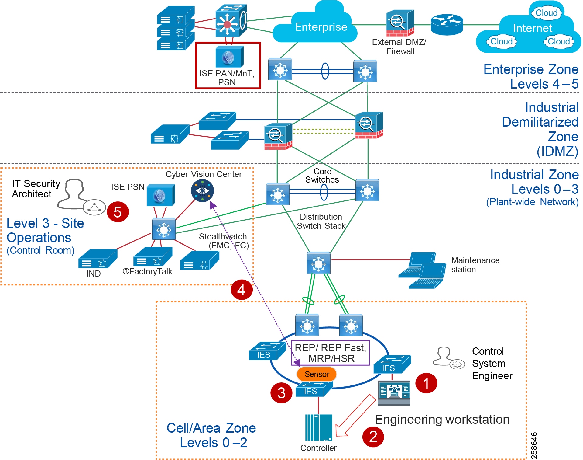
1. ![]() The control system engineer modifies or builds a new application in the engineering workstation.
The control system engineer modifies or builds a new application in the engineering workstation.
2. ![]() The control system engineer pushes the program to the controller.
The control system engineer pushes the program to the controller.
3. ![]() The Cisco Cyber Vision Sensor deployed in the Cell/Area Zone detects the event.
The Cisco Cyber Vision Sensor deployed in the Cell/Area Zone detects the event.
4. ![]() The Cisco Cyber Vision Sensor sends that event to the Cisco Cyber Vision Center.
The Cisco Cyber Vision Sensor sends that event to the Cisco Cyber Vision Center.
5. ![]() The IT security architect reviews the alert and determines the legitimacy of the event.
The IT security architect reviews the alert and determines the legitimacy of the event.
OT Managed Remote Access to Plant Floor
This use case describes how a remote user employee or partner can access a networking device or an IACS asset from either the internet or the Enterprise zone. The Securely Traversing IACS Data Across the Industrial Demilitarized Zone Design and Implementation Guide (for best practices, see Previous and Related Documentation for links to the Industrial Automation IDMZ CVD) provides design considerations and implementation details for providing remote access. The high-level steps for the remote access solution in that CVD as described in Figure 82 are:
1. ![]() A remote VPN gateway (ASA firewall) is enabled with a VPN group that authenticates a remote user and authorizes a service, which in this case is to access a remote desktop gateway in the IDMZ.
A remote VPN gateway (ASA firewall) is enabled with a VPN group that authenticates a remote user and authorizes a service, which in this case is to access a remote desktop gateway in the IDMZ.
2. ![]() The remote user, either an employee or partner, uses a remote access VPN client (Cisco AnyConnect) to connect to the remote VPN gateway and establishes a VPN session.
The remote user, either an employee or partner, uses a remote access VPN client (Cisco AnyConnect) to connect to the remote VPN gateway and establishes a VPN session.
3. ![]() From the remote VPN gateway a connection is established to the remote desktop gateway in the IDMZ.
From the remote VPN gateway a connection is established to the remote desktop gateway in the IDMZ.
4. ![]() From the remote desktop gateway, a connection is established to the Terminal Server with FactoryTalk applications in the Level_3 - Site Operations.
From the remote desktop gateway, a connection is established to the Terminal Server with FactoryTalk applications in the Level_3 - Site Operations.
Figure 82 Remote User Access in Industrial Automation Network
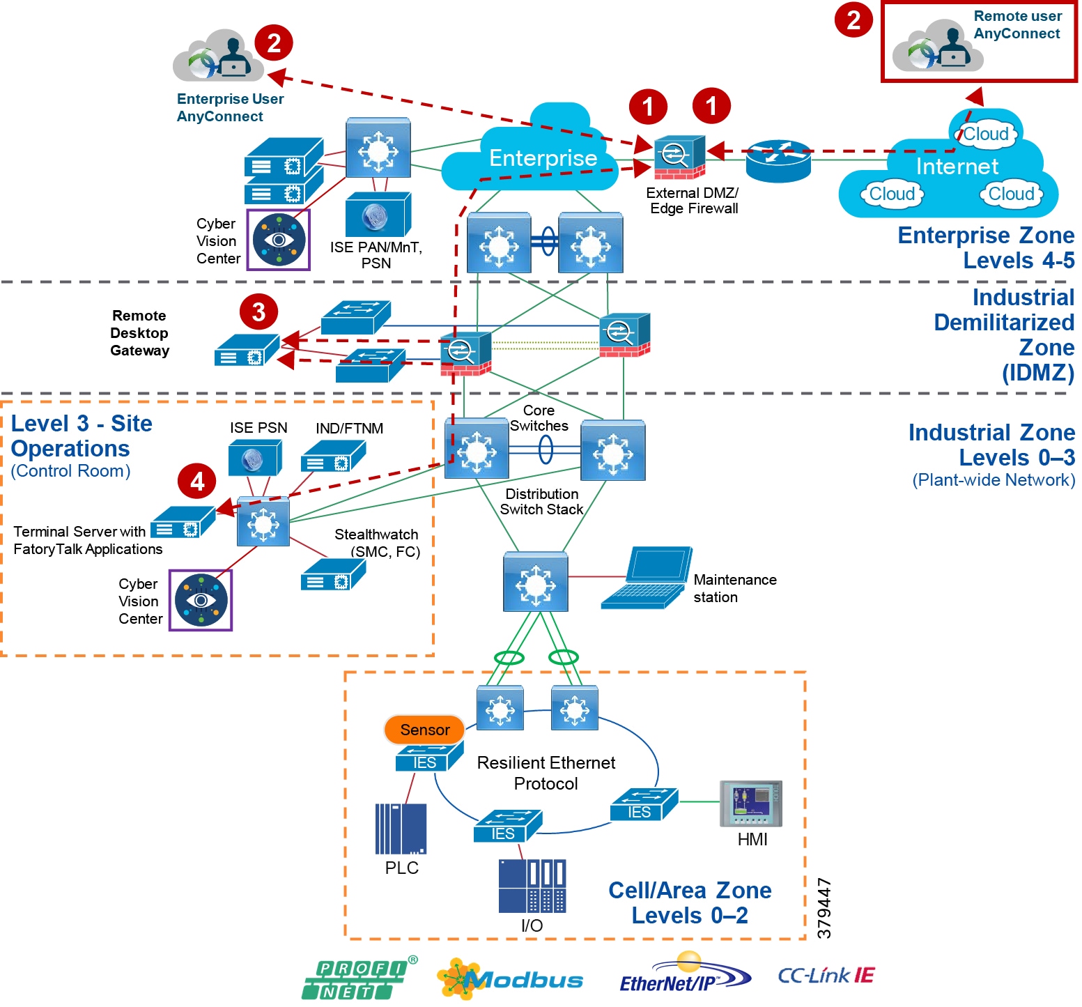
This use case builds on the previous Securely Traversing IACS Data Across the Industrial Demilitarized Zone CVD and expands the remote user use case by providing the means for an OT control system engineer to influence the remote access. In the previous CVD, when a remote user needs access an OT control system engineer opens a request to IT security architect to enable remote access for IACS assets. The remote user than accesses the desired IACS asset. However, when the remote user no longer needs access to the IACS asset, then the OT control system engineer must open another case for removing access. This process works, but when access is not removed in a timely manner, the risk of a security breach increases.
The ISE and Cisco Cyber Vision integration via pxGrid provides a way for an OT control system engineer to govern device access by modifying the assetTag of the IACS asset. When an OT control system engineer changes the group of the IACS asset, ISE updates the profile for the asset and the SGT (and communication restrictions) updates. When the IACS asset is put back in the original group, the remote access to the asset is revoked through the same profiling update. Figure 83 shows the group information of an asset.
Figure 83 Modifying the Group Information of an IACS Asset
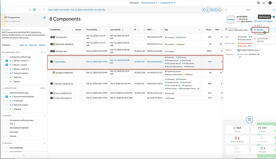
In this Industrial Automation CVD, the remote access use case is demonstrated by creating a separate group called Remote. A device that needs remote access needs to be moved to this group and when such an action is performed the following events are triggered:
1. ![]() The Cisco Cyber Vision sends a new device attribute "Remote" to ISE, which is linked to the "assetGroup" field in ISE. Refer to the implementation guide.
The Cisco Cyber Vision sends a new device attribute "Remote" to ISE, which is linked to the "assetGroup" field in ISE. Refer to the implementation guide.
2. ![]() ISE classifies this device as Remote_Access and issues a Change of Authorization for the IACS asset. This triggers a new authentication and authorization, which results in a new SGT assignment. Refer to the implementation guide.
ISE classifies this device as Remote_Access and issues a Change of Authorization for the IACS asset. This triggers a new authentication and authorization, which results in a new SGT assignment. Refer to the implementation guide.
3. ![]() The Cisco Catalyst 9300 distribution switch downloads the new SGACL from the ISE to allow access to the IACS device. Refer to the implementation guide.
The Cisco Catalyst 9300 distribution switch downloads the new SGACL from the ISE to allow access to the IACS device. Refer to the implementation guide.
4. ![]() Once the access to the IACS asset is no longer needed, the OT control system engineer moves the IACS asset back to the original group.
Once the access to the IACS asset is no longer needed, the OT control system engineer moves the IACS asset back to the original group.
5. ![]() Cisco Cyber Vision communicates the new group information to ISE, which triggers another reauthentication and reauthorization, placing the IACS asset back in its original profile of "Level_1_Controller". Refer to the implementation guide.
Cisco Cyber Vision communicates the new group information to ISE, which triggers another reauthentication and reauthorization, placing the IACS asset back in its original profile of "Level_1_Controller". Refer to the implementation guide.
6. ![]() The Cisco Catalyst 9300 distribution switch has an existing policy that denies communication from Remote_Access to Level_1_Controller, so the remote communication is blocked.
The Cisco Catalyst 9300 distribution switch has an existing policy that denies communication from Remote_Access to Level_1_Controller, so the remote communication is blocked.
Note: When a new SGT is assigned to an IACS asset there will be a temporary loss of connectivity for few seconds before applications can communicate with the IACS asset.
Device Onboarding
This section discusses the different scenarios related to managing an IACS asset as it is attached to the network. The scenarios described here are the following:
■![]() A new IACS asset attached to the IES
A new IACS asset attached to the IES
■![]() An onboarded IACS asset is moved to a different port in the IES
An onboarded IACS asset is moved to a different port in the IES
■![]() An onboarded IACS asset goes offline and comes back
An onboarded IACS asset goes offline and comes back
■![]() A defective IACS asset is replaced
A defective IACS asset is replaced
Onboarding a New IACS Asset
Onboarding a new IACS asset successfully means the following in this CVD:
■![]() The IACS asset is scanned successfully by the Cisco Cyber Vision.
The IACS asset is scanned successfully by the Cisco Cyber Vision.
■![]() ISE learns about the IACS asset information from Cisco Cyber Vision using the pxGrid probe.
ISE learns about the IACS asset information from Cisco Cyber Vision using the pxGrid probe.
■![]() The IACS asset has successfully completed port-based authentication and authorization to ISE and receives an appropriate SGT.
The IACS asset has successfully completed port-based authentication and authorization to ISE and receives an appropriate SGT.
■![]() The IACS asset initiates traffic flows both intra-Cell/Area Zone and inter-Cell/Area Zone.
The IACS asset initiates traffic flows both intra-Cell/Area Zone and inter-Cell/Area Zone.
■![]() The distribution switch (Cisco Catalyst 9300) is able to download the policy matrix from ISE and then enforce the traffic flows generated by the IACS asset.
The distribution switch (Cisco Catalyst 9300) is able to download the policy matrix from ISE and then enforce the traffic flows generated by the IACS asset.
■![]() The SMC is able to detect the traffic flows initiated by the IACS asset and generates an alarm if there is any malicious behavior generated by the IACS asset.
The SMC is able to detect the traffic flows initiated by the IACS asset and generates an alarm if there is any malicious behavior generated by the IACS asset.
When all of the above activities are completed, then this solution assumes that the IACS asset is onboarded successfully in the network. When all the activities are completed, an IT security architect has accomplished the following objectives:
■![]() Visibility of the IACS asset-Device type, Location (where it is connected), IP address, MAC address
Visibility of the IACS asset-Device type, Location (where it is connected), IP address, MAC address
■![]() Segmentation of the IACS asset-Enforce the Policy Matrix and control access to and from the IACS asset.
Segmentation of the IACS asset-Enforce the Policy Matrix and control access to and from the IACS asset.
■![]() Flow detection-Gain full visibility of the communications to and from the IACS asset.
Flow detection-Gain full visibility of the communications to and from the IACS asset.
■![]() Malware detection-Protect the IACS asset or other devices in the network from an infected device. The IT security architect would gain an understanding of the source of the infection and can develop and execute an immediate remediation plan.
Malware detection-Protect the IACS asset or other devices in the network from an infected device. The IT security architect would gain an understanding of the source of the infection and can develop and execute an immediate remediation plan.
In the above sequence, it is important to understand which part of the tasks are automated and where there is a dependency on the engineer in deploying the solution. The following tasks are performed when a new IACS asset attaches to the network:
■![]() Asset Discovery—Cisco Cyber Vision passively monitors whenever there is any new IACS device added to the Cell/Area Zone. And as a result, when a new IACS device is added to the network, the device attribute information is learned by Cyber Vision and this information is sent to ISE using pxGrid API.
Asset Discovery—Cisco Cyber Vision passively monitors whenever there is any new IACS device added to the Cell/Area Zone. And as a result, when a new IACS device is added to the network, the device attribute information is learned by Cyber Vision and this information is sent to ISE using pxGrid API.
■![]() Profiling of the IACS asset by the ISE-The profiling policies are expected to be configured on ISE (refer to the the implementation guide) and when an IACS asset needs to be authenticated and authorized, ISE matches the policies and applies the appropriate authorization profile (refer to the implementation guide). There is no manual intervention needed and this process happens as per the design. However, if ISE did not learn about the IACS asset from the Cisco Cyber Vision and the IACS asset came online before that event, then ISE can only apply a default policy to the IACS asset.
Profiling of the IACS asset by the ISE-The profiling policies are expected to be configured on ISE (refer to the the implementation guide) and when an IACS asset needs to be authenticated and authorized, ISE matches the policies and applies the appropriate authorization profile (refer to the implementation guide). There is no manual intervention needed and this process happens as per the design. However, if ISE did not learn about the IACS asset from the Cisco Cyber Vision and the IACS asset came online before that event, then ISE can only apply a default policy to the IACS asset.
■![]() When ISE learns new attributes for the IACS asset it reprofiles and issues a Change of Authorization (CoA) to the IACS asset. This process triggers a new instance of authentication and authorization to the ISE and reassigns the SGT value for the device.
When ISE learns new attributes for the IACS asset it reprofiles and issues a Change of Authorization (CoA) to the IACS asset. This process triggers a new instance of authentication and authorization to the ISE and reassigns the SGT value for the device.
■![]() NetFlow is enabled on all the ports where an IACS asset can connect. So, whenever a new IACS asset is connected the traffic flow is automatically captured in the Flow Collector. There is no need for manual intervention by either OT control system engineer or by IT security architect.
NetFlow is enabled on all the ports where an IACS asset can connect. So, whenever a new IACS asset is connected the traffic flow is automatically captured in the Flow Collector. There is no need for manual intervention by either OT control system engineer or by IT security architect.
■![]() SMC also monitors if there is any malicious behavior happening in the network by enabling several machine learning algorithms on the NetFlow data collected. This process also happens automatically and there is no manual intervention needed.
SMC also monitors if there is any malicious behavior happening in the network by enabling several machine learning algorithms on the NetFlow data collected. This process also happens automatically and there is no manual intervention needed.
Figure 84 shows a detailed process flow diagram for onboarding a new IACS asset.
Figure 84 Process Flow Diagram for On-boarding a New IACS Asset
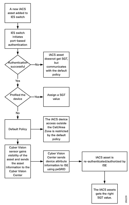
An Onboarded IACS Asset Moves to a Different Port in an IES
This section discusses the behavior of the network when an IACS asset is moved to a different port on an IES. This example is for an IACS asset that is currently on-boarded, authenticated, authorized, and has an SGT assignment, that is then moved to a different port in the IES. The assumption is that the new port has an identical configuration to the previous one. In this scenario, the following steps will happen:
■![]() The port-based authentication (refer to the implementation guide) will authenticate any device attached to it. So, the IACS asset needs to re-authenticate to the ISE.
The port-based authentication (refer to the implementation guide) will authenticate any device attached to it. So, the IACS asset needs to re-authenticate to the ISE.
■![]() ISE sees that the new device is already profiled and it matches the IP Address and MAC address, so it authorizes the IACS asset and issues the same SGT value it had in the prior port.
ISE sees that the new device is already profiled and it matches the IP Address and MAC address, so it authorizes the IACS asset and issues the same SGT value it had in the prior port.
■![]() The IACS device will have the same access as it had prior to being moved.
The IACS device will have the same access as it had prior to being moved.
An Onboarded IACS Asset Goes Offline and Comes Back
This section describes a situation where an onboarded IACS asset goes offline and comes back to the network. The underlying assumptions are similar to the previous section. The IACS asset before going offline was assigned a SGT and was communicating to other devices based on the Policy Matrix. Once the device comes back the following are the sequence of the events:
1. ![]() If the IACS asset is present in the endpoint data store, then the authentication and authorization will happen in normal fashion. By default, the IACS assets are saved permanently in the PSN data base. So even if the IACS asset comes back after a longer duration, the IACS asset can retain its former privileges.
If the IACS asset is present in the endpoint data store, then the authentication and authorization will happen in normal fashion. By default, the IACS assets are saved permanently in the PSN data base. So even if the IACS asset comes back after a longer duration, the IACS asset can retain its former privileges.
2. ![]() If the IACS asset is purged from the endpoint data store for any reason, then the ISE will not be able to correctly profile the IACS asset and the default policy would be applied.
If the IACS asset is purged from the endpoint data store for any reason, then the ISE will not be able to correctly profile the IACS asset and the default policy would be applied.
3. ![]() If the IACS asset needs reprofiling, then the OT control system engineer needs to re-scan the device from IND (refer to the implementation guide) and then ISE will be able to correctly profile the device and restore its former access.
If the IACS asset needs reprofiling, then the OT control system engineer needs to re-scan the device from IND (refer to the implementation guide) and then ISE will be able to correctly profile the device and restore its former access.
Replacement of a Failing IACS Asset
This section describes the workflow items that need to be performed by an OT control system engineer to replace a defective IACS asset.
1. ![]() The new IACS asset needs to be connected to the same port where the previous IACS asset was connected.
The new IACS asset needs to be connected to the same port where the previous IACS asset was connected.
2. ![]() Cisco Cyber Vision passively monitors whenever there is any new IACS device added to the Cell/Area Zone. And as a result, when a new IACS device is added to the network, the device attribute information is learned by Cisco Cyber Vision and this information is sent to ISE using pxGrid API.
Cisco Cyber Vision passively monitors whenever there is any new IACS device added to the Cell/Area Zone. And as a result, when a new IACS device is added to the network, the device attribute information is learned by Cisco Cyber Vision and this information is sent to ISE using pxGrid API.
3. ![]() ISE re-profiles the device, issues a CoA, and assigns the SGT to the IACS asset.
ISE re-profiles the device, issues a CoA, and assigns the SGT to the IACS asset.
4. ![]() Only the OT control system engineer is required for the whole process, the rest of the infrastructure is automatic and the only process that needs to be done by the OT control system engineer is to install the new asset and connect it to the switch.
Only the OT control system engineer is required for the whole process, the rest of the infrastructure is automatic and the only process that needs to be done by the OT control system engineer is to install the new asset and connect it to the switch.
Industrial Zone—Site Operations and Control Reference
The main focus of Industrial Automation is the validation of the Cell/Area Zone platforms, namely the Cisco IE and Cisco Catalyst 9300 switches.
The Industrial Zone reference architecture in Figure 82 highlights the services (not all) deployed at the operations and control Level 3 within Industrial Automation. Key additions for the architecture are the Cisco Catalyst products at the core and distribution layer, as well as visibility and security management platforms.
This level represents the functions required within Level 3 of the Purdue model and aligns with the core/distribution of the Enterprise networking model. The Industrial Site Operations and Control zone provides the Industrial applications and servers such as Historians, asset management, plant floor visualization, monitoring, and reporting. These applications would run on a plant or industrial data center. Network management and security services are deployed at this level including IND, ISE, and Stealthwatch, which are described in OT Intent-Based Networking Security. This level provides the networking functions to route traffic between the Cell/Area Zones and the applications within the Site Operations and Control. The core and distribution would run Layer 3 routing protocols to support plantwide connectivity and provide the following key functions:
■![]() Interconnecting the various Cell/Area IACS networks
Interconnecting the various Cell/Area IACS networks
■![]() Interconnecting the Level 3 site manufacturing systems
Interconnecting the Level 3 site manufacturing systems
■![]() Providing network management and security services to the Level 0 to 3 systems and devices
Providing network management and security services to the Level 0 to 3 systems and devices
■![]() Interface to the Plant Industrial DMZ
Interface to the Plant Industrial DMZ
Figure 85 Site Operations and Control

Industrial Site Operations and Control Characteristics
The majority of industrial plant facilities have a very different physical environment at this layer of the architecture compared to the Cell/Area Zone Level 2 and below. The networking characteristics are less intensive with respect to realtime performance for the industrial protocols and equipment is physically situated in an environmentally controlled area, cabinet or room.
The following highlight the key design considerations for Site Operations and Control which directly impact platform selection, network topology, security implementation, and overall design:
■![]() Industrial Characteristics-Environmental conditions, plant layout, and cabling costs all impact the platform choices and network topology in the design. Detailed earlier, the Cell/Area Zone in Industrial plants and processing facilities generally require physically hardened platforms. The general location and management strategy changes at Level 3. The networking platforms and servers housing the applications to support the plant are usually housed in environmentally controlled areas rather than the plant floor. This changes the dynamic of the platform choice which aligns with that of the traditional IT platforms such as the Cisco Catalyst 9500, Cisco Catalyst 9300, and Cisco Catalyst 9200 products and Cisco non-hardened UCS platforms housing the IACS, security, and network management applications.
Industrial Characteristics-Environmental conditions, plant layout, and cabling costs all impact the platform choices and network topology in the design. Detailed earlier, the Cell/Area Zone in Industrial plants and processing facilities generally require physically hardened platforms. The general location and management strategy changes at Level 3. The networking platforms and servers housing the applications to support the plant are usually housed in environmentally controlled areas rather than the plant floor. This changes the dynamic of the platform choice which aligns with that of the traditional IT platforms such as the Cisco Catalyst 9500, Cisco Catalyst 9300, and Cisco Catalyst 9200 products and Cisco non-hardened UCS platforms housing the IACS, security, and network management applications.
■![]() Interoperability and Interconnectivity-Within the Industrial Zone one of the key requirements required at this level is to provide internetworking for inter Cell/Area Zone and plant wide communications. Layer 3 is required to connect the various Cell/Area Zones with Site Operations and Control and provide a path from the IDMZ. Core and distribution layer switches will provide this routing and align with any performance or QoS requirements that may be required for inter-Cell/Area Zone traffic.
Interoperability and Interconnectivity-Within the Industrial Zone one of the key requirements required at this level is to provide internetworking for inter Cell/Area Zone and plant wide communications. Layer 3 is required to connect the various Cell/Area Zones with Site Operations and Control and provide a path from the IDMZ. Core and distribution layer switches will provide this routing and align with any performance or QoS requirements that may be required for inter-Cell/Area Zone traffic.
■![]() Real-time communications, Determinism, and Performance-Packet delay and jitter within an IACS network can have significant impact on the underlying industrial process, however at Level 3 Site Operations and Control this requirement is very different to that of the Cell/Area Zone. Critical I/O real time traffic is generally restricted to the Cell/Area Zone. Inter-locking PLC type traffic may traverse between the Cell/Area Zone so QoS models should be configured at this layer to facilitate prioritization of this traffic. The general performance criteria is less sensitive to packet delay, latency, and jitter as the majority traffic flows between the Site Operations level 3 and the Cell/Area Zones are generally non-real time from an industrial application perspective.
Real-time communications, Determinism, and Performance-Packet delay and jitter within an IACS network can have significant impact on the underlying industrial process, however at Level 3 Site Operations and Control this requirement is very different to that of the Cell/Area Zone. Critical I/O real time traffic is generally restricted to the Cell/Area Zone. Inter-locking PLC type traffic may traverse between the Cell/Area Zone so QoS models should be configured at this layer to facilitate prioritization of this traffic. The general performance criteria is less sensitive to packet delay, latency, and jitter as the majority traffic flows between the Site Operations level 3 and the Cell/Area Zones are generally non-real time from an industrial application perspective.
■![]() Availability-A key metric within industrial automation is overall equipment effectiveness (OEE). Availability is still a critical requirement of the network at this Level 3. Although the applications at this layer may be more resilient to network outages than the Cell/Area Zone, it is still important that they are available to maintain operations within the Cell/Area Zone. Resilient networking protocols and QoS need to be addressed to support the traffic traversing the Layer 3 boundaries.
Availability-A key metric within industrial automation is overall equipment effectiveness (OEE). Availability is still a critical requirement of the network at this Level 3. Although the applications at this layer may be more resilient to network outages than the Cell/Area Zone, it is still important that they are available to maintain operations within the Cell/Area Zone. Resilient networking protocols and QoS need to be addressed to support the traffic traversing the Layer 3 boundaries.
■![]() Security-Security, safety, and availability are tightly aligned within an industrial security framework. When discussing industrial network security, customers are concerned with how to keep the environment safe and operational. It is recommended to follow an architectural approach to securing the control system and process domain.
Security-Security, safety, and availability are tightly aligned within an industrial security framework. When discussing industrial network security, customers are concerned with how to keep the environment safe and operational. It is recommended to follow an architectural approach to securing the control system and process domain.
■![]() Recommended models would be the Purdue Model of Control Hierarchy, International Society of Automation 95 (ISA95) and IEC 62443, NIST 800-82 and NERC CIP for utility substations. Key security features are configured at this Level 3 to support the Cell/Area Zone including device and IACS asset visibility, secure access to the network, segmentation and grouping of assets. Network hardening (control plane and data plane) are configured to protect the infrastructure.
Recommended models would be the Purdue Model of Control Hierarchy, International Society of Automation 95 (ISA95) and IEC 62443, NIST 800-82 and NERC CIP for utility substations. Key security features are configured at this Level 3 to support the Cell/Area Zone including device and IACS asset visibility, secure access to the network, segmentation and grouping of assets. Network hardening (control plane and data plane) are configured to protect the infrastructure.
■![]() Management- Within the Industrial Zone and Site Operations and Control layer there needs to be a consistent management strategy. Where the Cell/Area Zone was operationally focused with a mixture of OT and IT personae, the Operations and Control Level 3 has security and IT platforms which drive a higher IT skillset. Network management and security needs a combination of security architects, IT personnel, and OT controls engineers to work in unison across a common network management framework.
Management- Within the Industrial Zone and Site Operations and Control layer there needs to be a consistent management strategy. Where the Cell/Area Zone was operationally focused with a mixture of OT and IT personae, the Operations and Control Level 3 has security and IT platforms which drive a higher IT skillset. Network management and security needs a combination of security architects, IT personnel, and OT controls engineers to work in unison across a common network management framework.
■![]() Traffic types-The traffic flows at this level in Site Operations and Control will predominantly support IACS applications such as Historians, asset management, IACS alarms and reporting, and network and security management applications (ISE, NetFlow, IND discovery). Multicast traffic seen supporting the IACS applications in the Cell/Area Zone does not leave the Cell/Area Zone so is not seen at this level.
Traffic types-The traffic flows at this level in Site Operations and Control will predominantly support IACS applications such as Historians, asset management, IACS alarms and reporting, and network and security management applications (ISE, NetFlow, IND discovery). Multicast traffic seen supporting the IACS applications in the Cell/Area Zone does not leave the Cell/Area Zone so is not seen at this level.
Site Operations and Control Level 3 Components
The model above depicts a medium to large plant model which utilizes a classic enterprise networking model concept. There is a core and distribution within the Level 3 domain which provides the plant-wide networking through regular routing protocols such as EIGRP or OSPF. The core provides connectivity into the "plant data center" where the Cisco UCS would house the industrial applications and the network management and security functions for the industrial facility (Level 3 and below). These core switches would provide connectivity for communications to/from the Industrial DMZ.
Within the Industrial data center a Cisco Catalyst 3850 or Cisco Catalyst 9300 provides the connectivity for the servers deployed in the data center. A Cisco UCS is deployed to provide the physical hardware for the virtually hosted applications. The Cisco Catalyst 9300 switch highlighted previously in the Cell/Area Zone components provided connectivity for the Industrial Data center in this phase. However, any data center design needs to consider the performance requirements of the applications hosted and the network requirements to support these applications.
Cisco Site Operations and Control Hosted Applications
Cisco Security Platforms
■![]() Cisco ISE-As previously described, ISE is deployed in the industrial data center. The ISE PSN sits at this layer. It provides asset authentication, authorization, provisioning, profiling, and posturing services. The PSN applies access policies to connected devices.
Cisco ISE-As previously described, ISE is deployed in the industrial data center. The ISE PSN sits at this layer. It provides asset authentication, authorization, provisioning, profiling, and posturing services. The PSN applies access policies to connected devices.
■![]() Cisco Stealthwatch-Stealthwatch is hosted in the industrial data center. It improves threat defense with network visibility and security analytics. It collects and analyzes massive amounts of data to give even the largest, most dynamic networks comprehensive internal visibility and protection.
Cisco Stealthwatch-Stealthwatch is hosted in the industrial data center. It improves threat defense with network visibility and security analytics. It collects and analyzes massive amounts of data to give even the largest, most dynamic networks comprehensive internal visibility and protection.
Network Management
Cisco IND-IND can be hosted in the industrial data center. It will manage and communicate with assets and networking equipment in the Cell/Area Zones, providing visibility into the IACS assets attached to the network. IND supports industrial automation protocols such as CIP, PROFINET, OPC-UA, Modbus, BACnet, and so on to discover automation devices such as PLC, IO, HMI, and drives and delivers an integrated topology map of automation and networking assets to provide a common framework for operations and plant IT personnel to manage and maintain the industrial network.
Cisco DNA Center was not validated in this phase of Industrial Automation, however it can be positioned as the management platform for the Cisco Catalyst products. This aligns with the tool requiring a more IT-aware knowledge base, necessitating working in conjunction with control engineers and the industrial requirements.
Time Synchronization
Time synchronization is critical for event and data analysis with correlation across the entire industrial infrastructure. However there are cases where islands of time may be maintained per Cell/Area Zone. Network Timing Protocol (NTP) or Precision Time Protocol (PTP) must be enabled on all infrastructure components to ensure consistent timing is maintained and event correlation can be provided plantwide. This should be enabled at Level 3 across the entire industrial zone into the Cell/Area Zones.
Common Network-based Services
■![]() DNS—Within the plant environment a dedicated DNS server is usually deployed for applications within the Industrial Zone.
DNS—Within the plant environment a dedicated DNS server is usually deployed for applications within the Industrial Zone.
■![]() DHCP—DHCP services could be deployed across the Industrial Zone, however within the wired IACS devices the IP addressing is usually statically defined. See Cell/Area Zone IP Addressing.
DHCP—DHCP services could be deployed across the Industrial Zone, however within the wired IACS devices the IP addressing is usually statically defined. See Cell/Area Zone IP Addressing.
■![]() Domain Controller/Directory Services—These are typically dedicated to the Industrial zone, but could be synchronized with the Enterprise via the IDMZ architecture. The CPwE IDMZ CVD has details about the replicated services between the Enterprise and the Industrial Zone for EtherNet/IP environments.
Domain Controller/Directory Services—These are typically dedicated to the Industrial zone, but could be synchronized with the Enterprise via the IDMZ architecture. The CPwE IDMZ CVD has details about the replicated services between the Enterprise and the Industrial Zone for EtherNet/IP environments.
High Level Network Design
Critical I/O real time traffic is generally restricted to the Cell/Area Zone. Inter-locking PLC type traffic may traverse between the Cell/Area Zone, so QoS models should be configured at this layer to facilitate prioritization of this traffic. The general performance criteria is less sensitive to packet delay, latency, and jitter as the majority traffic flows between the Site Operations Level 3 and the Cell/Area Zones are generally non-real time from an industrial application perspective. Layer 3 is configured at this level and the Layer 3 network convergence times will need to be factored into supporting the traffic flows, but it is generally acknowledged that this will suffice.
High Availability
The following looks at core routing and Layer 3 switch resiliency. Layer 3 routing starts at the Level 3 from the distribution switches aggregating the Cell/Area Zones. The Level 3 Site Operations and Control traffic performance requirement is very different from the Cell/Area Zone and the Industrial Zone. Table 37 highlights Information/process times for typical traffic between the Cell/Area Zone and Control layer. Cycle times are in the second range, but this is product dependent so understanding the performance metrics of the applications must still be considered and factored into the network availability design.
| Requirement Class | Typical Cycle Time | Typical RPI | Connection Timeout |
|---|---|---|---|
| Information/Process (for example, HMI) | < 1 s | 100 - 250 ms | Product dependent |
| For example, 20 seconds for RSLinx | |||
| Time critical processes (for example, I/O) | 30 - 50 ms | 20 ms | 4 intervals of RPI, but =100 ms |
| Safety | 10 - 30 ms | 10 ms | 24 - 1000 ms |
| Motion | 500 μs - 5ms | 50 μs - 1 ms | 4 intervals |
The following provides high-level design guidance and recommendations with regard to availability for the Site Operations and Control Networking:
■![]() Layer 3 routing between the core and the distribution switches (large plant deployments)
Layer 3 routing between the core and the distribution switches (large plant deployments)
■![]() Redundant core and distribution routers with Active/Standby or virtual switch redundancy features and functions. This includes Stacking or HSRP for the Cisco Catalyst 9300 at the distribution, HSRP at the distribution for the Cisco IE 5000, and StackWise Virtual for the Cisco Catalyst 9500 in the Core.
Redundant core and distribution routers with Active/Standby or virtual switch redundancy features and functions. This includes Stacking or HSRP for the Cisco Catalyst 9300 at the distribution, HSRP at the distribution for the Cisco IE 5000, and StackWise Virtual for the Cisco Catalyst 9500 in the Core.
■![]() Layer 3 routing between the IDMZ and the core/distribution routers
Layer 3 routing between the IDMZ and the core/distribution routers
■![]() Redundant links throughout the architecture
Redundant links throughout the architecture
■![]() Configuration backups of all networking devices (Cisco IND can be used for the Cisco IE switches)
Configuration backups of all networking devices (Cisco IND can be used for the Cisco IE switches)
■![]() Network hardening best practices to protect the Management, Control, and Data planes of the network infrastructure
Network hardening best practices to protect the Management, Control, and Data planes of the network infrastructure
■![]() Segment IACS applications with similar dedicated functions or separating critical from non-critical applications into their own VLAN. An example would be to keep security and network management on a different VLAN to the industrial applications supporting the Cell/Area Zone. This promotes security and availability if hosts are infected so that the Layer 3 boundary devices can be deployed to protect devices outside of the infected VLAN.
Segment IACS applications with similar dedicated functions or separating critical from non-critical applications into their own VLAN. An example would be to keep security and network management on a different VLAN to the industrial applications supporting the Cell/Area Zone. This promotes security and availability if hosts are infected so that the Layer 3 boundary devices can be deployed to protect devices outside of the infected VLAN.
■![]() Layer 2 redundant star topologies described in the Cell/Area Zone are deployed for the server switch connectivity
Layer 2 redundant star topologies described in the Cell/Area Zone are deployed for the server switch connectivity
■![]() Dual NIC connectivity from the servers to the redundant switches. Dual NIC technologies from the Virtual servers.
Dual NIC connectivity from the servers to the redundant switches. Dual NIC technologies from the Virtual servers.
■![]() Server, virtual server, and application redundancy where required
Server, virtual server, and application redundancy where required
■![]() IDMZ to prevent unauthorized access to and from the Industrial zone
IDMZ to prevent unauthorized access to and from the Industrial zone
Management
There is a shift in the support model at the Level 3 for the network infrastructure. Generally, at Level 3 and above there is more of an IT awareness in the support staff. Security applications that are deployed require a higher IT skillset. This does not detract from the fact that the network still needs to be intuitive and easy to support. The following are guidelines and high-level design recommendations to help support the management of the network infrastructure:
■![]() Implement a separate out-of-band management network where possible; at a minimum provide a dedicated management VLAN.
Implement a separate out-of-band management network where possible; at a minimum provide a dedicated management VLAN.
■![]() Logging is a cornerstone of a sound security and network management strategy. The network infrastructure needs to be configured with logging capabilities and reporting functions to a centralized security management system. Syslogs, along with SNMPv3, should be enabled to report any events or incidents discovered at the endpoints.
Logging is a cornerstone of a sound security and network management strategy. The network infrastructure needs to be configured with logging capabilities and reporting functions to a centralized security management system. Syslogs, along with SNMPv3, should be enabled to report any events or incidents discovered at the endpoints.
■![]() Although not validated, Cisco DNA Center or Cisco Prime Infrastructure can manage the Cisco Catalyst products positioned at this layer. You can manage the Cisco Catalyst 9000 series switches using the Cisco IOS software Command-Line Interface (CLI), using Cisco Prime® Infrastructure 3.1.7 DP13, Cisco DNA Center, onboard Cisco IOS XE software web user interface, SNMP, or Netconf/YANG.
Although not validated, Cisco DNA Center or Cisco Prime Infrastructure can manage the Cisco Catalyst products positioned at this layer. You can manage the Cisco Catalyst 9000 series switches using the Cisco IOS software Command-Line Interface (CLI), using Cisco Prime® Infrastructure 3.1.7 DP13, Cisco DNA Center, onboard Cisco IOS XE software web user interface, SNMP, or Netconf/YANG.
■![]() UCS server management recommendations are outside the scope of this document. The management of the physical and virtual servers in the industrial data center are specific to platform choice, storage architecture, and Virtualization vendor.
UCS server management recommendations are outside the scope of this document. The management of the physical and virtual servers in the industrial data center are specific to platform choice, storage architecture, and Virtualization vendor.
Security
Segmentation
■![]() Within the industrial data center, segment IACS applications with similar dedicated functions or separating critical from non-critical applications into their own VLAN.
Within the industrial data center, segment IACS applications with similar dedicated functions or separating critical from non-critical applications into their own VLAN.
■![]() Policy enforcement using Cisco Cyber Vision, Cisco ISE, and TrustSec as per the Cell/Area Zone use case for advanced segmentation. Policy enforcement and segmentation are administered at the distribution switch in Industrial Automation.
Policy enforcement using Cisco Cyber Vision, Cisco ISE, and TrustSec as per the Cell/Area Zone use case for advanced segmentation. Policy enforcement and segmentation are administered at the distribution switch in Industrial Automation.
■![]() For deployments where TrustSec is not deployed, ACLs should be used to provide the security policies for the domain.
For deployments where TrustSec is not deployed, ACLs should be used to provide the security policies for the domain.
■![]() Enabling NetFlow on all the NetFlow-capable switches in Level 3, core, distribution, and the industrial data center and exporting to Steathwatch will provide a plantwide view of application and network traffic. This can be used to help provide a baseline traffic profile and used to help identify anomalies in the network data flows.
Enabling NetFlow on all the NetFlow-capable switches in Level 3, core, distribution, and the industrial data center and exporting to Steathwatch will provide a plantwide view of application and network traffic. This can be used to help provide a baseline traffic profile and used to help identify anomalies in the network data flows.
Network Hardening
Secure the Control Plane, Management Plane, and Data Plane following the premise and guidance outlined in Network Hardening—A Component of System Integrity.
Server Hardening Practices and Endpoint Security
The following are examples of server hardening practices:
■![]() Patching and upgrading operating systems-To reduce vulnerability to attacks, systems should be patched to the latest vendor-recommended software and firmware levels. Patches should be tested before implementation. A plan for implementation of patches should be considered.
Patching and upgrading operating systems-To reduce vulnerability to attacks, systems should be patched to the latest vendor-recommended software and firmware levels. Patches should be tested before implementation. A plan for implementation of patches should be considered.
■![]() Removing or disabling unnecessary services, applications, and network protocols
Removing or disabling unnecessary services, applications, and network protocols
■![]() OS user authentication—Use the least privilege access.
OS user authentication—Use the least privilege access.
■![]() Host-based IDS and vulnerability scanning and endpoint security. When implementing, consider the impact of the security systems on application performance.
Host-based IDS and vulnerability scanning and endpoint security. When implementing, consider the impact of the security systems on application performance.
■![]() Secure networking protocols-SFTP (Secure File Transport Protocol), SCP (Secure Copy), and SSH (Secure Shell), and SNMPv3
Secure networking protocols-SFTP (Secure File Transport Protocol), SCP (Secure Copy), and SSH (Secure Shell), and SNMPv3
■![]() Backup or redundant databases
Backup or redundant databases
■![]() Redundant servers and networking to support the availability of the applications
Redundant servers and networking to support the availability of the applications
Site-wide Precise Time—Design Considerations
This section describes site-wide precise time based on IEEE 1588-2008 Precision Time Protocol version 2 (PTPv2). The section starts with the business value of precise time, describes other timing concepts, outlines the basic PTP architecture, and provides design considerations and recommendations to deploy site-wide precise time.
Note: Readers should review the relevant sections that introduce precision time standards and profiles, such as:
■![]() Time Synchronization
Time Synchronization
■![]() PTP over PRP
PTP over PRP
–![]() Configuring PTP over PRP
Configuring PTP over PRP
–![]() Troubleshooting PTP over PRP
Troubleshooting PTP over PRP
■![]() Cisco IE 5000 as PTP Grandmaster
Cisco IE 5000 as PTP Grandmaster
–![]() Configuring PTP Grandmaster
Configuring PTP Grandmaster
–![]() Troubleshooting PTP Grandmaster
Troubleshooting PTP Grandmaster
Introduction
Why Precise Time
The Industrial Automation solution is an important foundation for industrial companies driving IoT and Industry 4.0 initiatives. By securely connecting IACS systems, devices, and applications, the solution enables access to rich amounts of data to drive IoT applications such as Predictive Maintenance, Digital Twin, and Big-Data analytics. That data is significantly more valuable when it is understood precisely when the data is produced. These IoT analytic applications can then derive better results (for example, causality) based on consistent and precise time awareness.
Additionally, the key IACS applications that this solution was designed to support increasingly require precise time to perform their operations. PTP provides a common (i.e., network-based) precise time that applications can use to act and analyze sensed information from a range of devices. IACS standards and protocols are beginning to adopt PTP to support a range of functions, such as Sequence of Events and Motion Control applications. Examples of that include the ODVA, Inc.'s Common Industrial Protocols Sync function (CIP-Sync), OPC Foundations Unified Architecture, and IEC's 61850 for Substation Automation.
Industry control systems typically have the time precision requirements shown in Table 38.1
| Applications | Accuracy | Comment |
|---|---|---|
| Electrical substations | 10 µs | Absolute time |
| Electrical grids | 1 µs | Absolute time |
| Motion control | 500 µs - 5 ms | Four intervals |
| Drive | 1 µs | Relative time |
| IO | 30 - 50 ms | Four intervals of RPI |
| Safety | 10 - 30 ms | Four intervals of RPI |
NTP, IRIG-B, and PTP are three typical time synchronization protocols developed to meet the above requirements, as shown in Table 39.2
| Protocol | Media | Accuracy |
|---|---|---|
| NTP | Ethernet | 50 - 100 ms |
| IRIG-B | Coaxial | 1 - 10 ms |
| PTP | Ethernet | 20 - 100 ns |
Due to customer and application requirements for more time-aware applications and data, this solution now supports the site-wide distribution of precise time as a feature.
Other Timing Technologies
Synchronizing devices and applications in a network is not a new problem and has been addressed in several ways. Many IT applications, with lower precision requirements, use the Network Time Protocol (NTP). For industrial applications, either GPS was used for specific devices or IRIG was used to distribute time in an overlay network. IRIG is based on deploying an overlay network, which adds significant costs. Now, PTP has solved the problem of distributing precise time on converged, open, standard networks. Before PTP, achieving high precision required proprietary communication standards and overlay networks (for example, IRIG-B). Here is a brief summary of timing technologies:
■![]() Global Positioning System (GPS)—Precise time and geo-location are achieved with devices that receive satellite-based signals. Other similar services are being developed by Russia (GLONASS), China (BeiDou), and Europe (Galileo).
Global Positioning System (GPS)—Precise time and geo-location are achieved with devices that receive satellite-based signals. Other similar services are being developed by Russia (GLONASS), China (BeiDou), and Europe (Galileo).
■![]() Inter-range instrumentation group time codes (IRIG)—Before PTP, this was the most prevalent means of distributing precise time across a network based on non-Ethernet, single-function technology.
Inter-range instrumentation group time codes (IRIG)—Before PTP, this was the most prevalent means of distributing precise time across a network based on non-Ethernet, single-function technology.
■![]() Network Time Protocol (NTP) —An open standard protocol (current version IETF RFC 5905) to distribute time commonly found in IT systems.
Network Time Protocol (NTP) —An open standard protocol (current version IETF RFC 5905) to distribute time commonly found in IT systems.
■![]() Synchronous Ethernet (SnycE)—An ITU-based method to distribute precise time over Ethernet commonly used in the telecommunications industry.
Synchronous Ethernet (SnycE)—An ITU-based method to distribute precise time over Ethernet commonly used in the telecommunications industry.
This solution is focused on distributing precise time via PTP across a site-wide network. In this architecture, GPS (or similar systems) or IRIG can be used to establish alignment with Coordinated Universal Time (UTC).
PTP Architecture Overview
The PTP (IEEE 1588v2) standard provides a series of mechanisms and algorithms to distribute time accurately while compensating for latency and jitter as the time is communicated over the network. The protocol operates in a hierarchical manner, establishing primary-subordinate relationships among devices where subordinates will synchronize their clocks with a primary clock. The IACS devices and IES maintain time synchronization by sending and receiving PTP event messages containing information that allows them to correct time differences between primary and subordinates.
The process that builds the clock hierarchy, determining what devices will be assigned as primary or subordinate, is done by using the Best Master Clock Algorithm (BMCA). When a PTP-capable clock joins the network, it will listen to PTP messages called PTP announce messages. These messages contain information such as time source, clock quality, and priority numbers. The BMCA runs continuously and uses the announce messages information to make these assignments and adjustments as necessary. The BMCA establishes the "grandmaster" clock and, depending on the configuration and capability of the network infrastructure, builds a hierarchy of primary and subordinate clocks which are used to distribute time.
Components
PTP identifies the following key roles to perform time distribution:
■![]() Grandmaster Clock (GM)
Grandmaster Clock (GM)
■![]() Ordinary Clock (OC)
Ordinary Clock (OC)
■![]() Transparent Clock (TC)
Transparent Clock (TC)
■![]() Boundary Clock (BC)
Boundary Clock (BC)
Grandmaster Clock (GMC)
The grandmaster clock is the primary source of time in the PTP domain. The GMC is chosen by the BMCA algorithm. GMCs should have high quality oscillators and be synchronized to UTC, for example from a GPS receiver.
■![]() For the site-wide distribution of precise time, we recommend customers to acquire specific "grandmaster" devices, multiple for resiliency, and operate them as part of the manufacturing/site-wide application level of the network architecture.
For the site-wide distribution of precise time, we recommend customers to acquire specific "grandmaster" devices, multiple for resiliency, and operate them as part of the manufacturing/site-wide application level of the network architecture.
Or:
■![]() Establish two Cisco IE 5000 aggregation switches as GMCs with appropriate access to GPS (or similar satellite-based time) or IRIG connectivity to align with UTC.
Establish two Cisco IE 5000 aggregation switches as GMCs with appropriate access to GPS (or similar satellite-based time) or IRIG connectivity to align with UTC.
Ordinary Clock (OC)
An ordinary clock is a device that has a single PTP port. It functions as an end-node in the PTP topology. Any clock can be selected by the BMCA as a primary or subordinate within the PTP domain depending on the presence of other clocks. Ordinary clocks are the most common clock type in a PTP system because they are used as end nodes in the system. Typical examples of ordinary clocks in an IACS application are a Programmable Automation Controller (PAC) or an I/O device.
Boundary Clock (BC)
A Boundary Clock (BC) is a multi-PTP port device (for example, IE switches). The BCs, along with Transparent Clocks, distribute time through the network. When not chosen as the Grandmaster, a boundary clock's port on which the Grandmaster can be reached becomes a "subordinate" port. As a subordinate clock, the BC synchronizes its internal clock to the primary. The boundary clock then becomes a primary to IACS and network devices connected to the other ports. Other clocks connected to these ports will become subordinates to the BC and synchronize to the BC's internal clock. A BC relieves the GM from having to respond to every OC clock's PTP messages, which is an important scaling consideration.
BCs can also be configured to infinitely persist time-properties received from the GMC, which is beneficial when the GM is unavailable, either due to device outages or connectivity loss. In this situation, the BC maintains consistent time distribution services helping maintain the availability of any IACS relying upon those services. In this case, customers should also consider network devices that are designed to provide consistent quality time over extended periods, for example have Temperature Compensated Crystal Oscillators (a.k.a. TCXO) or Oven-controller Crystal Oscillator (OCXO, for example, Cisco IE 5000s are Stratum 3E). BCs can also be used to distribute PTP into different VLANs.
BC clocks also tend to take longer to start up and re-configure when the GM clock timing configurations change, require more configuration, and tend to introduce more drift as the depth of BCs increases.
Transparent Clock (TC)
Transparent Clocks (TC) are another means by which network infrastructure devices distribute time. TCs measure and account for the delay in a time-interval field in network timing packets, making the switches temporarily transparent to the other primary and subordinate nodes on the network. TCs compensate for latency across the network by inserting delay corrections into the PTP packets. TCs do not become nodes in the PTP hierarchy and are therefore neither primary or subordinate clocks. TCs sit in-line between the primary and subordinate clocks and provide time correction between these devices.
There are two types of transparent clocks defined in the PTPv2 specification:
■![]() End-to-end (E2E) transparent clocks compensate for latency across a network by measuring how long the devices in the network take to process and forward the PTP packets. These measurements are added to the correction field in the PTP packets. This mechanism works on both brownfield, where some network infrastructure devices do not support PTP and greenfield, where all network infrastructure devices support PTP scenarios
End-to-end (E2E) transparent clocks compensate for latency across a network by measuring how long the devices in the network take to process and forward the PTP packets. These measurements are added to the correction field in the PTP packets. This mechanism works on both brownfield, where some network infrastructure devices do not support PTP and greenfield, where all network infrastructure devices support PTP scenarios
■![]() Peer-to-peer (P2P) transparent distributes the delay measurement across the network which suggests all devices must be PTP compliant. P2P TCs are not compatible with E2E TCs. P2P is specified as part of the Utility profile and used in the Substation use cases. P2P TCs are not used in CI Sync applications.
Peer-to-peer (P2P) transparent distributes the delay measurement across the network which suggests all devices must be PTP compliant. P2P TCs are not compatible with E2E TCs. P2P is specified as part of the Utility profile and used in the Substation use cases. P2P TCs are not used in CI Sync applications.
TC clocks also tend to more quickly start up and re-configure when the GM clock timing configurations change, require little configuration, and tend to maintain more precise time as they scale.
This site-wide precise time distribution design recommends TCs using E2E for access-level switches.
Resiliency
As mentioned earlier, Precise Time is becoming a critical network-based function for Industrial Automation and Control applications and the associated IoT applications accessing them. Therefore, it is critical that the precise timing function is available and consistent for production operations. This section reviews resiliency considerations for PTP.
Grandmaster Clock
A functioning grandmaster is a requirement for consistent delivery of precise time in a network. The BMCA ensures that a grandmaster is chosen and, if connectivity or service is lost, another is chosen quickly, within a second or two. This solution recommends redundant third-party grandmaster devices in the manufacturing zone of the network to provide consistent time. Additionally, the solution recommends setting priorities in the network infrastructure to ensure a certain order of grandmaster "failover" in the case that connectivity or service is lost to the specific GM devices. Our recommendation is to establish the following GM priority for the BMCA:
1. ![]() Third-party grandmasters
Third-party grandmasters
2. ![]() Core switches
Core switches
3. ![]() Aggregation switches
Aggregation switches
4. ![]() Controller devices with GM capability
Controller devices with GM capability
In combination with the time-property persist setting, this ensures a single grandmaster is available as long as some network connectivity is available and that as network connectivity and/or third-party GM services are restored, that the PTP services are available and consistent, avoiding disruption to IACS systems that rely upon it. See Site-wide PTP Design Considerations for more details.
Network Infrastructure
Much of this Industrial Automation solution has been dedicated to describing network resiliency in the core, aggregation, and access layers. In particular the use of Layer 2 resiliency protocols such as Etherchannel and ring protocols (for example, Resilient Ethernet Protocol—REP, Spanning Tree, MRP, DLR, PRP, and HSR) as well as network resiliency features such as virtual switching, switch stacking, and HSRP for Layer 3 functions.
Unfortunately, PTP is not supported on all of these protocols and features. PTP is currently not supported on Etherchannel links, HSR, MRP, virtual switch bundles, stacked switches, or Layer 3 links. This solution recommends establishing separate, single-path Layer 2 connections between the GMCs in the manufacturing zone and over the core switches to the aggregation switches. Although there may be single-points of failure of connectivity to the manufacturing zone GMCs, the priority and BMCA configuration ensure quality devices are ready to take over GM functions quickly until connectivity and service are re-established.
In this way, PTP services can be site-wide distributed over resilient network infrastructure and topologies that provide highly-resilient network and precise time services. The solution does recommend distributing precise time in Spanning Tree or REP managed ring/multipath Cell/Area zone topologies. The Substation Automation solution, applying the Power profile, makes use of PTP over PRP topologies.
Additionally, to support site-wide PTP, we recommend that customers maintain resilient aggregation and core networking services based on HSRP between matched switches.
Components
The components used to test site-wide precision time distribution are shown in Table 40.
| Product Role | Product | Software Version | Remarks |
|---|---|---|---|
| Access | Cisco IE 4000 | 15.2(7)E0s | Unit Under Test (UUT)—Boundary and Transparent Clock E2E |
| Access | Cisco IE 3000 | 15.2(7)E0s | UUT—Transparent Clock E2E |
| Access | Cisco IE 3400 | 16.11.1a(ED) | UUT—Transparent Clock E2E |
| Distribution | Cisco IE 5000 | 15.2(7)E0s | UUT— Boundary Clock |
| Core Switch | Cisco Catalyst 9300 | 16.9.2 | UUT—Boundary Clock |
| Grandmaster clock | MeinBerg LANTime M600 | 6.24.021 | Third-party GPS-based GM |
| PTP Analysis Tool | Calnex Paragon-X | 27.10.40 | PTP protocol/performance analyzer |
Architecture Summary
The above sections outlined the key components in a PTP architecture. For site-wide distribution of precise time, this document suggests the following:
■![]() Specialized third-party GMCs are installed in the manufacturing zone. For resiliency reasons, two GMCs are recommended. Each GMC should support and be connected to external antennae to receive GPS (or similar services) to align the clock with UTC.
Specialized third-party GMCs are installed in the manufacturing zone. For resiliency reasons, two GMCs are recommended. Each GMC should support and be connected to external antennae to receive GPS (or similar services) to align the clock with UTC.
■![]() Cisco IE 5000s can perform as GMCs in certain scenarios, especially smaller networks with collapsed core/aggregation switching.
Cisco IE 5000s can perform as GMCs in certain scenarios, especially smaller networks with collapsed core/aggregation switching.
■![]() Use core and aggregation switches that support PTP, specifically default profile and configured to be Boundary Clocks within the PTP hierarchy. These devices can then distribute PTP into multiple Cell/Area Zones within the site or production facility.
Use core and aggregation switches that support PTP, specifically default profile and configured to be Boundary Clocks within the PTP hierarchy. These devices can then distribute PTP into multiple Cell/Area Zones within the site or production facility.
■![]() Access switches can be configured to be E2E TCs to distribute time to an IACS VLAN.
Access switches can be configured to be E2E TCs to distribute time to an IACS VLAN.
Note: This design only supports distribution of time into one VLAN over a set of access switches supporting a Cell/Area Zone.
Figure 86 depicts the site-wide precise time architecture.
Figure 86 Site-wide Precise Time Architecture
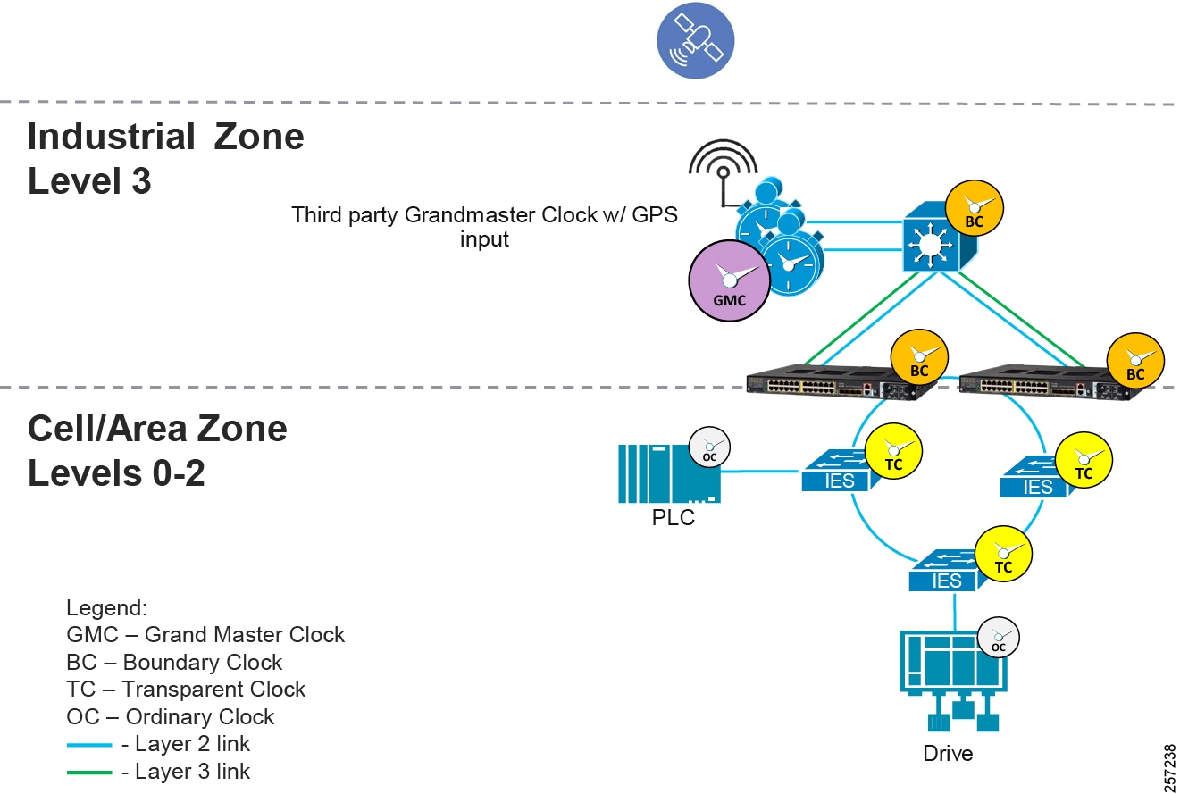
Site-wide PTP Design Considerations
Refer to the following for additional information:
■![]() IEEE 1588 Precise Time Protocol
IEEE 1588 Precise Time Protocol
■![]() Deploying Scalable Time Distribution within a Converged Plantwide Ethernet Architecture
Deploying Scalable Time Distribution within a Converged Plantwide Ethernet Architecture
https://www.cisco.com/c/en/us/td/docs/solutions/Verticals/CPwE/5-1/STD/DIG/CPwE-5-1-STD-DIG.html
■![]() Substation Automation Local Area Network and Security Cisco Validated Design
Substation Automation Local Area Network and Security Cisco Validated Design
https://www.cisco.com/c/en/us/td/docs/solutions/Verticals/Utilities/SA/2-3-2/CU-2-3-2-DIG.html
Best Master Clock Algorithm
This is the process that builds the PTP clock hierarchy, determining what devices will be assigned as primary or subordinate, is done by using the Best Master Clock Algorithm (BMCA). In essence, it works in a similar manner to Spanning Tree Protocol. The GM is somewhat like a root switch and all primary/subordinate settings are established based on that. When a PTP network is operational, all devices are started and synchronized. Moving the GM due to connectivity or device availability issues should not disrupt the level of synchronization if the network infrastructure has good oscillators to hold consistent time and the time meta-data does not change. The primary/subordinate ports may change depending on the location of the GM, but the synchronization stays stable. This effect is measured and reported in the the implementation guide.
When a PTP-capable clock joins the network, it will listen to PTP messages called PTP announce messages. These messages will contain information such as time source, clock quality, and priority numbers. Customers should ensure PTP devices that join the network are configured with appropriate priority settings to avoid unwanted devices becoming GM and potentially impacting the PTP operations. The BMCA runs continuously and uses the announce message information to make these assignments and adjustments as necessary. We recommend the following structure for site-wide precise time:
Grandmaster (GM) Tier
The grandmaster tier contains the designated grandmasters for the PTP domain. For site-wide precision time distribution it is recommended to select a third-party device to be the primary grandmaster and redundant for resiliency. This device should have an accurate and reliable clock and ideally be synchronized to UTC using a reference clock. The primary grandmaster should be protected from faults such as power failures to improve stability of the PTP domain. It is also recommended to designate a secondary grandmaster which should use the same PTP timescale and UTC offset to minimize impact to IACS applications when the secondary grandmaster becomes the grandmaster. However, failing over from a primary grandmaster to a secondary grandmaster and vice versa may cause disruptions to time synchronization.
For smaller production facilities, a Cisco IE 5000 switch can also act as grandmaster as they are designed to receive GPS or IRIG timing signals.
The specified grandmaster device(s) should have the BMCA priority1 value set low so that they win the BMCA election. The priority2 value should be used to differentiate between the primary and secondary grandmasters with the primary having the lowest priority2 value.
Infrastructure Tier
The network infrastructure tier consists of core, aggregation, and access switches. The infrastructure should have the priority1 value set so first the core switches become GM if the GM devices are unreachable. Subsequently the aggregation switches should become GM if the core switches are unreachable. In addition, the ptp time-property persist infinite command should be applied to all switches configured as boundary clocks to preserve the time properties when the redundant GMC comes out of standby to prevent subordinate clocks from detecting a variance in the time values.
It is recommended to provide power protection to the infrastructure tier to improve overall IACS application reliability. Engineers should consider installing the infrastructure in separate enclosures (if appropriate) with dedicated power supplies and backup batteries.
Controller Tier
The controller tier is designed to reduce time synchronization issues when the network is down, such as when the control panel is powered on as IACS devices take different amounts of time to start up. Some IACS devices like Programmable Automation Controllers (PAC) feature battery backed real-time clocks and will continue to keep time when the power is disconnected. These IACS devices should have their priority1 value set so they become grandmaster until connectivity to the network is restored. This reduces the chance of a device without a real-time clock becoming grandmaster and setting an arbitrary time, like January 1 1970 00:00:00. Some IACS devices such as FactoryTalk Historian ME modules may fault if they detect an IACS application time that is significantly earlier than the time logged for existing data points.
Device Tier
The device tier contains all other PTP-aware IACS devices. Most of these IACS devices exclude battery backed real-time clocks and will revert to some known epoch on startup, such as January 1 1970 00:00:00. Therefore, they should not be relied on as a grandmaster clock. Their priority1 and priority2 values should be set so they will not become the grandmaster. The device tier is likely to contain most of the IACS devices in the plant- wide IACS architecture. The overhead of configuring the system can be reduced by using the default priority1 and priority2 value of 128 for the IACS devices in the device tier.
Table 41 shows an example of the priority settings that establish the above recommendations.
| | | |
| GM1 | 1 | 1 |
| GM2 (backup) | 1 | 2 |
| Core Switch BC | 10 | 11 |
| Core Switch BC (backup) | 10 | 12 |
| Aggregation Switch BC | 100 | 101 |
| Aggregation Switch BC (backup) | 100 | 102 |
| Access Switch BC | 110 | 111 |
| Access Switch BC (backup) | 110 | 112 |
| Ordinary Clocks—PLC (Time module) | 120 | 120 |
| Ordinary Clocks—IACS | 128 | 128 |
Grandmaster Configuration
These recommendations are for devices intended to perform the GMC function:
■![]() Third-party GM device PTP message update interval should align with IES and PLC and be compliant with customer PLC performance requirements.
Third-party GM device PTP message update interval should align with IES and PLC and be compliant with customer PLC performance requirements.
■![]() IES GNSS is supported only on Cisco IE 5000 switches with SKUs that have Version ID (VID) v05 or higher, GNSS is available as a timing source for PTP default and power profiles only.
IES GNSS is supported only on Cisco IE 5000 switches with SKUs that have Version ID (VID) v05 or higher, GNSS is available as a timing source for PTP default and power profiles only.
■![]() If IES PTP grandmaster clock loses the antenna signal, the clock quality will degrade, resulting in a GM switchover.
If IES PTP grandmaster clock loses the antenna signal, the clock quality will degrade, resulting in a GM switchover.
■![]() GNSS receiver comes up in self-survey mode and attempts to lock on to a minimum of four different satellites to obtain a 3-D fix on its current position. It computes nearly 2000 different positions for these satellites, which takes about 35 minutes. The timing signal obtained during self-survey mode can be off by 20 seconds; therefore, Cisco IOS collects PPS only during OD mode.
GNSS receiver comes up in self-survey mode and attempts to lock on to a minimum of four different satellites to obtain a 3-D fix on its current position. It computes nearly 2000 different positions for these satellites, which takes about 35 minutes. The timing signal obtained during self-survey mode can be off by 20 seconds; therefore, Cisco IOS collects PPS only during OD mode.
■![]() The participating grandmaster clock, switches, and subordinate devices should be in the same domain.
The participating grandmaster clock, switches, and subordinate devices should be in the same domain.
Network Infrastructure—PTP Port Settings
As PTP is a critical network function, it should be handled with high priority and appropriately marked with in the QoS fields of the VLAN tag. Therefore we recommend that each PTP capable network infrastructure be configured as tagged packets by entering the global vlan dot1q tag native command.
Table 42 shows the port-based PTP setting recommendations for network infrastructure in PTP default profile and in either BC or TC mode.
| PTP Port Interface Characteristic | What it does | When to use | Recommended Setting |
|---|---|---|---|
| Announce interval | Establishes frequency of the BMCA runs | If the BMCA algorithm needs to run more or less frequently. Note: Should be consistent across the domain. | 1 (2 seconds, default) |
| Announce timeout | Time Interval to declare announce msg timeout | Specifies the time for announcing timeout messages as a factor of 2. | 3 (8 seconds, default) |
| delay-req interval | Interval to send delay-Req when ports is in primary state (device is subordinate) | Setting communicated to subordinates (for example, end devices with OC clock). This can improve startup synchronization time if device does not over-sample at startup. Increased number of delay requests can cause performance issues for TC clocks. | 0 (1 pps) |
| Sync interval | Changes frequency of Sync msgs transmits | The BC or GMC sends Sync msgs 1 per second. More frequent Syncs converge faster, but increase CPU utilization on OCs and BCs. Less frequent Syncs converge slower, but lower CPU utilization. | 0 (1 second, default) |
| Sync limit | Max offset until attempt to resync | Is only in effect when switch is in BC mode and applicable on subordinate port. When the subordinate port drifts beyond this limit, the switch BC will resync likely disrupting PTP services and applications relying on it. As subordinate port can change, recommend setting on all ports. | 10,000 ns |
| vlan | PTP VLAN on Trunk port | For BCs, change the 802.1Q tagged VLAN for PTP messages. Needs to be the same VLAN tag on both ends of Ethernet link. | 1-4094 |
Boundary Clock Configuration
Synchronization Algorithm
The boundary clock mode has three different transfer functions that change how the boundary clock adjusts for packet delay variation (PDV) as shown in Table 43. PDV is a measure of the difference in the one-way end-to-end delay of packets in a network flow and is a more precise description of what is commonly referred to network "jitter".
| Transfer Function | PDV Filtering | Time Convergence |
|---|---|---|
| Default (Linear) | Low | Average |
| Feedforward | None | Fast |
| Adaptive | High | Slow |
This solution recommends use of the feedforward transfer function for production environments. Because the feedforward transfer does not filter PDV, it should only be implemented in networks where all of the network infrastructure supports PTP in hardware.
The adaptive filter can be used in applications with high PDV such as 802.11 wireless LANs. It can also be used in applications where the network consists of non-PTP aware switches and high PDV.
Note: The adaptive filter does not meet the time performance requirements specified in ITU-T G.8261.
PTP VLAN
A switch in PTP BC mode has the ability to process PTP traffic from different VLANs. This is a key means by which PTP becomes a site-wide service, although it is a Layer 2 protocol. BCs are used to distribute a consistent PTP across the network to various VLANs and Cell/Area Zones.
■![]() Establish a PTP site-VLAN to distribute PTP from GM and across core and aggregation switches set in BC mode.
Establish a PTP site-VLAN to distribute PTP from GM and across core and aggregation switches set in BC mode.
■![]() Set the PTP VLAN on a trunk port. On trunk ports between the core and aggregation switches, this should be the PTP site-VLAN. On trunk ports to Cell-Area Zone (i.e., access switches), the VLAN is the IACS VLAN that needs PTP services.
Set the PTP VLAN on a trunk port. On trunk ports between the core and aggregation switches, this should be the PTP site-VLAN. On trunk ports to Cell-Area Zone (i.e., access switches), the VLAN is the IACS VLAN that needs PTP services.
■![]() In BC mode, only PTP packets in port-associated PTP VLAN will be processed, PTP packets from other VLANs will be dropped.
In BC mode, only PTP packets in port-associated PTP VLAN will be processed, PTP packets from other VLANs will be dropped.
■![]() Before configuring the PTP VLAN on an trunk interface, the PTP VLAN must be created and allowed on the trunk port.
Before configuring the PTP VLAN on an trunk interface, the PTP VLAN must be created and allowed on the trunk port.
■![]() When VLAN is disabled on the grandmaster clock, the PTP interface must be configured as an access port.
When VLAN is disabled on the grandmaster clock, the PTP interface must be configured as an access port.
■![]() Currently Cisco Catalyst 9300 platform PTP is supported only on VLAN-based SVI interfaces, not over Layer 3 links. Therefore additional Layer 2 links must be established to distribute PTP.
Currently Cisco Catalyst 9300 platform PTP is supported only on VLAN-based SVI interfaces, not over Layer 3 links. Therefore additional Layer 2 links must be established to distribute PTP.
Summary of Configuration Recommendations
■![]() Grandmaster Tier
Grandmaster Tier
–![]() Select a specific device to be a reliable grandmaster for the IACS applications. Connect it in the manufacturing zone directly to the core switches.
Select a specific device to be a reliable grandmaster for the IACS applications. Connect it in the manufacturing zone directly to the core switches.
–![]() Select a PTP domain to be used consistently throughout the site.
Select a PTP domain to be used consistently throughout the site.
–![]() Protect the grandmaster from faults such as power disruptions to increase stability of IACS applications.
Protect the grandmaster from faults such as power disruptions to increase stability of IACS applications.
–![]() Synchronize the grandmaster to UTC via GPS or similar technology.
Synchronize the grandmaster to UTC via GPS or similar technology.
■![]() Infrastructure Tier
Infrastructure Tier
–![]() Configure the PTP Domain to be consistent throughout the site.
Configure the PTP Domain to be consistent throughout the site.
–![]() Ensure consistent PTP VLAN configuration on all links where PTP is communicated.
Ensure consistent PTP VLAN configuration on all links where PTP is communicated.
–![]() Use switches in PTP boundary clock mode to propagate time between VLANs and across core and aggregation switches.
Use switches in PTP boundary clock mode to propagate time between VLANs and across core and aggregation switches.
–![]() On BC clock, use the feedforward transfer function and the sync limit (for example, 10,000) to improve synchronization across IACS applications.
On BC clock, use the feedforward transfer function and the sync limit (for example, 10,000) to improve synchronization across IACS applications.
–![]() On BC clock switches, use the ptp time-property persist infinite command to help ride through the loss of the grandmaster.
On BC clock switches, use the ptp time-property persist infinite command to help ride through the loss of the grandmaster.
–![]() Configure the switches to send PTP as tagged packets. Enter the global vlan dot1q tag native command.
Configure the switches to send PTP as tagged packets. Enter the global vlan dot1q tag native command.
–![]() Use switches in PTP E2E TC mode to propagate time on a ring or linear topology.
Use switches in PTP E2E TC mode to propagate time on a ring or linear topology.
–![]() Isolate and provide battery backed power to the switches to reduce Layer 2 and PTP topology changes.
Isolate and provide battery backed power to the switches to reduce Layer 2 and PTP topology changes.
–![]() Do not send PTP traffic over EtherChannels, virtual switches, stacked switches, or Layer 3 links.
Do not send PTP traffic over EtherChannels, virtual switches, stacked switches, or Layer 3 links.
■![]() Controller Tier
Controller Tier
–![]() Configure IACS devices with real-time clocks, such as PACs, to become the grandmaster if the network is down.
Configure IACS devices with real-time clocks, such as PACs, to become the grandmaster if the network is down.
■![]() Device Tier
Device Tier
–![]() Use the default priority1 and 2 values (i.e., 128) to simplify configuration.
Use the default priority1 and 2 values (i.e., 128) to simplify configuration.
Cross-Industry Applicability
This Industrial Automation solution encompasses networking, security, and data management applied to a wide range of industrial verticals and applications, providing a range of design and implementation alternatives that may be applicable to several industries. Although the size, vendors, applications, and devices may significantly vary among these facilities, many of the core networking and security concepts are applicable. For example, while high availability is a key requirement across all industrial use cases, oil and gas and utilities may have more stringent availability requirements than a manufacturing facility. Nonetheless, the CVD solution best practice guidance is applicable across many industries and industrial customer environments.
| | | | | | |
| Business Imperatives | Maximize uptime and quality Improve safety, security, and reliability Drive predictive maintenance, machine learning, and Digital Twin applications Connect factory to partners and suppliers | Retain and acquire customers Improve safety, security, and reliability Integrate new energy sources and consumption models Modernize the utility grid | Maximize uptime and quality Improve safety, security, and reliability Improve decision making and drive machine learning Connect Refinery and Pipeline to partners and suppliers | Increased mechanization through automated plant Improve safety, security, and reliability Optimization of material and equipment flow Improve anticipation of failure Monitoring of real-time performance | Maximize uptime and quality Improve safety, security, and reliability Drive predictive maintenance Monitoring of real-time performance |
Edge Compute with the Cisco IC3000 Industrial Compute Gateway
In the Internet of Things (IoT) space, devices at the edge require network connectivity to unleash value in the data these devices capture over time. Traditional networking infrastructure can provide this connectivity. Depending on the environment, more hardened industrial switching and routing hardware is required. Cisco offers a number of such devices that are fan-less, can withstand hot/harsh environments, and be deployed outside traditional networking cabinets. Devices such as Cisco Industrial Ethernet (IEx000) switches, Cisco Integrated Services Routers (IR8x9), and Cisco IC3000 Industrial Compute Gateways all provide hardened casings while performing different functions depending on the topology and the means of connectivity.
With network connectivity established, the very first question a networking engineer must answer is how to communicate with the edge devices above the Layer 3 network layer. Often what is required here is a compute device (such as an industrial PC) placed near the devices to communicate at the application/protocol level and extract the data from the devices. For this reason, Cisco introduced IOx. A compute environment exists within these devices and allows for the deployment of applications in the form of containers to extract device data.
Cisco IOx combines IoT application execution at the edge, secure connectivity with Cisco IOS, and powerful services for rapid, reliable integration with IoT sensors and the cloud, reducing for the need for external standalone compute deployments requiring additional management, space, and power. The advent of edge computing platforms offers many opportunities with Cisco IOx paving the way for innovative applications to emerge and demonstrate the wide-ranging capabilities of IoT.
Overview
Cisco IC3000 Industrial Compute Gateway extends data intelligence to the edge of the IoT network to seamlessly bridge the intent-based network and IoT data fabric in a complete end-to-end solution for applications such as intelligent roadways, smart factories, and so on.
■![]() See the Cisco Industrial Compute 3000 Data Sheet at:
See the Cisco Industrial Compute 3000 Data Sheet at:
https://www.cisco.com/c/en/us/products/collateral/routers/3000-series-industrial-compute-gateways/datasheet-c78-741204.html
■![]() The Cisco IC3000 is a device that can managed at scale using the Cisco IoT Field Networking Director product. See the data sheet at:
The Cisco IC3000 is a device that can managed at scale using the Cisco IoT Field Networking Director product. See the data sheet at:
https://www.cisco.com/c/en/us/products/cloud-systems-management/iot-field-network-director/index.html
Other related documentation includes:
■![]() Cisco IOx DevNet
Cisco IOx DevNet
https://developer.cisco.com/site/iox/
■![]() Cisco IOx DevNet Getting Started Documentation
Cisco IOx DevNet Getting Started Documentation
https://developer.cisco.com/site/iox/documents/developer-guide/?ref=quickstart
■![]() IOx App developer's guide on DevNet
IOx App developer's guide on DevNet
https://developer.cisco.com/site/iox/documents/developer-guide/
■![]() MTconnect is the communication standard
MTconnect is the communication standard
http://www.mtconnect.org/
The section is provided to guide the reader through the process of deploying an edge application on the Cisco IC 3000 with a Linux Containers (IOx Packaged/OVA/Docker) based application. To demonstrate the use of Cisco IOx, the open source MTConnect agent is described as a sample application.
The process will rely on the Cisco IoT Field Networking Director (FND) to deploy, manage, and monitor the application running on the IC3000. To demonstrate the capability of an MTConnect agent, two applications will be deployed on the Cisco IC3000:
■![]() The agent itself, which is an application that talks to an MTConnect-capable machine and makes the data visible to applications that need it via a REST interface.
The agent itself, which is an application that talks to an MTConnect-capable machine and makes the data visible to applications that need it via a REST interface.
■![]() A machine simulator, which feeds data into the agent in the absence of real machine data for demonstration purposes.
A machine simulator, which feeds data into the agent in the absence of real machine data for demonstration purposes.
As the Cisco IC3000 is a compute device, not a networking device, it is ready to run IOx out of the box without any additional configuration beyond what is needed for the application itself. Once deployed, it will be immediately ready to receive applications deployed on top of IOx environment at scale using the Cisco FND.
Use Cases/Services/Deployment Models
This section addresses the following technology use cases:
■![]() Edge Compute using Cisco IC 3000 with Cisco IOx and MTConnect agent as sample application.
Edge Compute using Cisco IC 3000 with Cisco IOx and MTConnect agent as sample application.
■![]() Application life cycle management at scale using Cisco FND and for individual devices using the IOx built-in Local Manager.
Application life cycle management at scale using Cisco FND and for individual devices using the IOx built-in Local Manager.
System Overview
By integrating the converged platform to the machine, downtime can be reduced and the Overall Equipment Effectiveness (OEE) can be improved. What Customer is Doing Today versus Cisco Converged Platform shows a typical customer deployment (on the left) versus Cisco's offering (on the right). This network represents a sample zone with machines connected to a Cisco IC 3000 which, in turn, is connected to the data center where an application such as OEE resides.
Digitally connecting machines provides manufacturers with a way to capture critical data on machine utilization. This is one of the most important metrics to gauge how productive an operation is. Cisco Edge Compute devices provide the necessary tools to integrate, capture, and share machine data with upstream applications.
Figure 87 What Customer is Doing Today versus Cisco Converged Platform
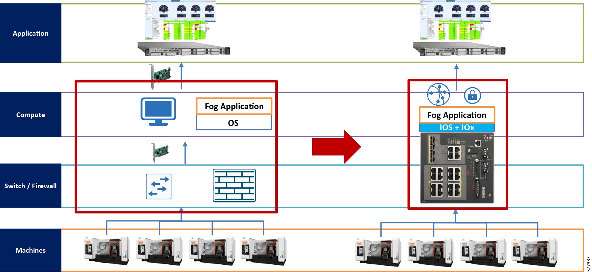
System Components
When Cisco IC3000 is deployed with an application like MTConnect, it communicates to various machines pulling streaming data. Since it is not a networking device, it needs to connect to a switch like the Cisco IE 2000 or Cisco IE 4000. The switches are managed by the Cisco Industrial Network Director and the Cisco IC3000s are managed with Cisco FND. as shown in Cisco IC3000 Deployment Topology.
Figure 88 Cisco IC3000 Deployment Topology
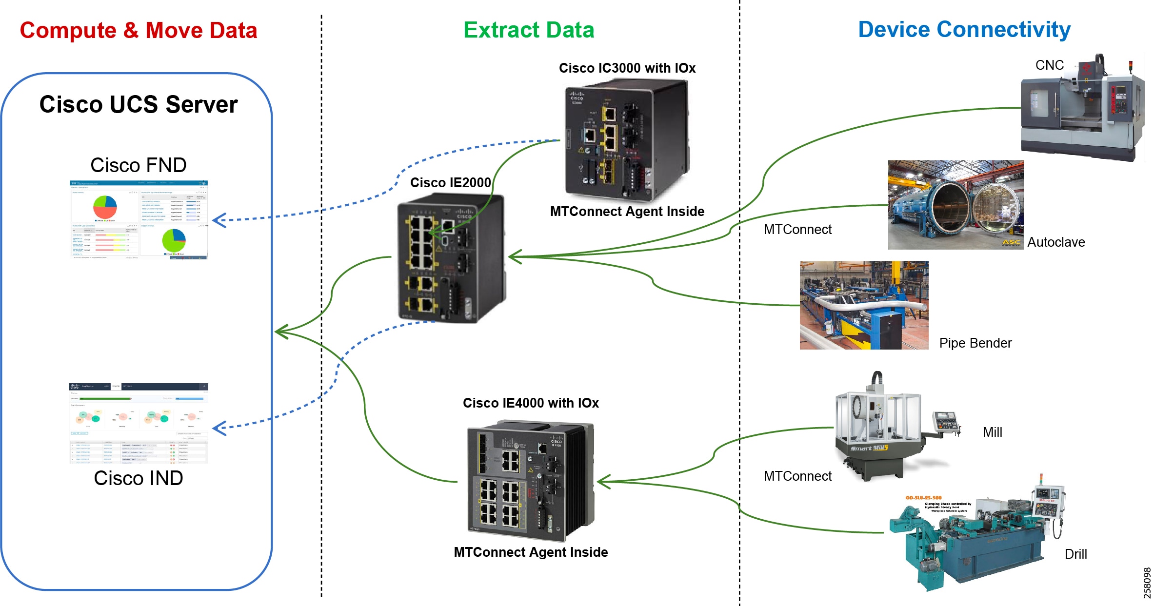
System Functional Considerations
As the Cisco IC3000 is an industrial PC capable of having four physical interfaces in addition to the management Ethernet interface, it is potentially possible to have applications use one or more of the physical interfaces for data traffic or even have multiple applications share the same physical interface if they will communicate on the same subnet. For MTConnect application, two versions of the application have been tested:
■![]() The first uses a single interface eth0 to communicate to the outside world (both machine side and enterprise side) using a single IP address.
The first uses a single interface eth0 to communicate to the outside world (both machine side and enterprise side) using a single IP address.
■![]() The second version has two interfaces, et0 and eth1. Each interface can be assigned to a physical interface, where each interface will be a different subnet. This is critical in situations where machines traffic isolation is necessary. The application will then communicate with the machine over one subnet using one physical interface and to the enterprise using a second subnet over a second physical interface.
The second version has two interfaces, et0 and eth1. Each interface can be assigned to a physical interface, where each interface will be a different subnet. This is critical in situations where machines traffic isolation is necessary. The application will then communicate with the machine over one subnet using one physical interface and to the enterprise using a second subnet over a second physical interface.
The choice of design depends on the requirements for the specific deployment.
Note: While MTConnect is used here as a sample app for the deployment steps, any IOx Packaged or Docker applications can be ported over to IOx and the deployment steps would be the same.
System Implementation
This section includes the following major topics:
■![]() Install Field Network Director
Install Field Network Director
■![]() IC3000 Bring Up and Application Install
IC3000 Bring Up and Application Install
Install Field Network Director
Cisco FND software can be installed one component at a time in an existing Linux OS. But a simpler way to install the software is to deploy the fully inclusive OVA file Cisco provides on CCO, using VMware ESXi 5.5/6.0 environment. You must download FND version 4.5.1-5 or higher for proper support of IC3000 code.
For instructions on the OVA installation in ESXi, refer to:
https://www.cisco.com/c/en/us/td/docs/routers/connectedgrid/iot_fnd/install/ova/installation_ova.html
Once deployed, you can log in to the server at https://ip using the default credentials for the UI (root/root123). When asked to change the password, create a new password and login using the new password.
At this point the software is ready to create device configurations for the devices that will be managed by the server. The process is done using an csv file with the serial numbers of the IC3000 devices that will be added. An example of such a file with one IC3000 is:
The contents of the file are:
■![]() eid—PID VID + Serial number off the IC3000 label
eid—PID VID + Serial number off the IC3000 label
■![]() devicetype—IC3000
devicetype—IC3000
■![]() lat,lng—Represents the geo coordinates where the device is located.
lat,lng—Represents the geo coordinates where the device is located.
■![]() IOxUserName—Creates a user name which will be used to access the devices IOx.
IOxUserName—Creates a user name which will be used to access the devices IOx.
■![]() IOxUserPassword—Assigns a password to the IOxUser defined for the device (minimum eight characters).
IOxUserPassword—Assigns a password to the IOxUser defined for the device (minimum eight characters).
Note: The user ID and password will be used by FND to access the IOx on the device, but the user can also use these credentials to login in the Local Manager interface for the device. It is important to make sure the password defined is at least eight characters and has capital and special characters.
Next upload this csv file in FND under Devices -> Add devices -> Upload and ensure the UI reports success after uploading. At this point an IC3000 with any of the serial numbers that were imported will be able to communicate with this FND and download a configuration for the group of devices it belongs to or the default configuration. A configuration captures a number of items for a device such as heartbeat frequency, but mainly it tells the device which physical interfaces are to be enabled and the NTP server it will use to synchronize its clock going forward. This last step is very critical as it is the only means to set the clock of an IC3000 running in production mode with FND. Sample FND Default Device Configuration is an example of such a configuration which enables two of the four physical interfaces and adds one NTP server as preferred.
Figure 89 Sample FND Default Device Configuration
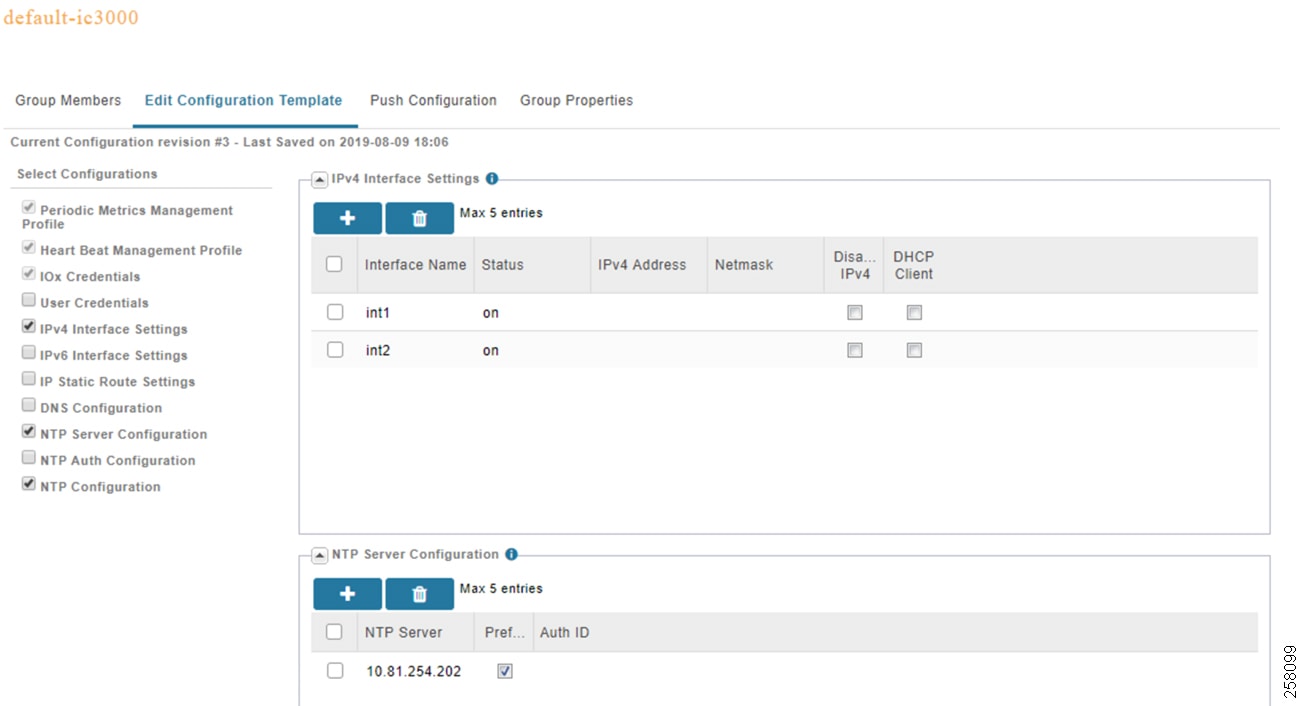
IC3000 Bring Up and Application Install
IC3000 Boot Up and FND Connectivity
The boot up process described below is referred to as Production Mode, in which the IC3000 is managed by FND. If the device is brought up without FND, it is called developer mode. Refer to Troubleshooting for more info on developer mode.
Each IC3000 needs to have its management interface connected to a DHCP-capable network device. This is because DHCP will provide critical pieces of information for this management interface in addition to the IP address. Currently the IP address of this interface must be assigned through DHCP and not statically. If a specific IP address needs to be assigned, then it is possible to use the host and client-identifier statements under the DHCP pool in IOS to force a specific address for a specific IC3000. Below is an example of IOS DHCP pool configurations to allow an IC3000 to register with FND where its serial number has been imported. The critical statements below are option 43 which specifies the IP address and port of the FND server (192.168.0.175:9125).
Note: It is no longer necessary to use option 42 to provide a ntp server IP as FND will provide it as shown above. If option 42 is provided, it will be ignored.
Once an IC3000 device is rebooted with this DHCP config, it will register with FND server and it should show up under the list of Up devices and its color will be green (see A Registered IC3000 in FND). Also, the physical interfaces on this IC3000 which are being enabled by the downloaded configuration should also turn green to indicate they are active when connected to another device (a switch for example). The IC3000 is now ready to have IOx applications installed.
Figure 90 A Registered IC3000 in FND
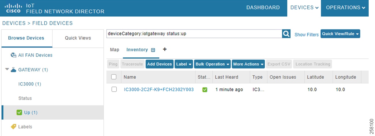
IC3000 Firmware Upgrade
If the IC3000 software version is Factory Default (1.0.1), you need to upgrade to version 1.1.1 to gain access to the latest features and fixes. The upgrade is done on all FND connected IC3000s at once that belong to same group. The upgrade steps are:
1. ![]() Make sure the ADMIN -> Provisioning Settings -> IoT-FND URL point to the FND server by IP or by name if reachable by DNS.
Make sure the ADMIN -> Provisioning Settings -> IoT-FND URL point to the FND server by IP or by name if reachable by DNS.
2. ![]() In CONFIG -> Firmware Update -> Images, select IC3000 from left panel and upload new image.
In CONFIG -> Firmware Update -> Images, select IC3000 from left panel and upload new image.
3. ![]() In CONFIG -> Firmware Update -> Groups, make sure that all IC3000s to upgrade belong to the same group, click Upload Image, and select the IC3000 image to upload to all devices.
In CONFIG -> Firmware Update -> Groups, make sure that all IC3000s to upgrade belong to the same group, click Upload Image, and select the IC3000 image to upload to all devices.
4. ![]() In CONFIG -> Firmware Update, select the Group in the previous step and click Install Image. This step will install the image downloaded. Note that an upgrade could take 15 min if it requires a firmware upgrade and not just an IOx upgrade.
In CONFIG -> Firmware Update, select the Group in the previous step and click Install Image. This step will install the image downloaded. Note that an upgrade could take 15 min if it requires a firmware upgrade and not just an IOx upgrade.
Note: If the upgrade fails for some reason, a device reset might be necessary (see IC3000 Reset).
Application Install and Configuration
The following steps install the MTConnect Agent application on one or many IC3000 devices at once. Unlike app installation via the Local Manager, the steps below install, activate, and start an app automatically with no further user intervention.
1. ![]() From the APPS tab in FND, select Import Apps to first add the app in the FND catalog. Here you are given an option to Import an app as an IOx SDK Packaged container, as an OVA, or from a Docker registry. The steps below assume an application tar file packaged with IOx SDK.
From the APPS tab in FND, select Import Apps to first add the app in the FND catalog. Here you are given an option to Import an app as an IOx SDK Packaged container, as an OVA, or from a Docker registry. The steps below assume an application tar file packaged with IOx SDK.
2. ![]() Browse for the app file on the local machine and click Upload to store the app on FND.
Browse for the app file on the local machine and click Upload to store the app on FND.
3. ![]() From APPS tab in FND, choose app and click Install.
From APPS tab in FND, choose app and click Install.
4. ![]() Select one or more devices, then click Add Selected Devices to install list.
Select one or more devices, then click Add Selected Devices to install list.
5. ![]() Click Next> to configure the app.
Click Next> to configure the app.
6. ![]() It is possible to customize a number of features on this screen, but we will only check the networking to make sure we are using int1(bridge) interface in Dynamic mode. Once selected, click REASSIGN NETWORKS to apply the change.
It is possible to customize a number of features on this screen, but we will only check the networking to make sure we are using int1(bridge) interface in Dynamic mode. Once selected, click REASSIGN NETWORKS to apply the change.
7. ![]() If asked to Configure VCPUs, select a value from 1-4 and click REASSIGN VCPU to confirm.
If asked to Configure VCPUs, select a value from 1-4 and click REASSIGN VCPU to confirm.
8. ![]() Click Done Let's Go to complete the install.
Click Done Let's Go to complete the install.
9. ![]() Repeat the same process for the Simulator app if needed.
Repeat the same process for the Simulator app if needed.
Note: While the deployed device configuration to IC3000 activated two interfaces, both MTConnect agent app and the simulator app require only one interface for operation. A version of the MTConnect agent app also exists which uses two interfaces if the deployment requires machine and enterprise segment separation.
Application Uninstall
To uninstall an application on one or many IC3000 devices at once:
1. ![]() From the Apps tab in FND, choose the application to uninstall and click Uninstall.
From the Apps tab in FND, choose the application to uninstall and click Uninstall.
2. ![]() Select one or more devices, then click Add Selected Devices to the uninstall list.
Select one or more devices, then click Add Selected Devices to the uninstall list.
3. ![]() Click Done Let's Go to complete the uninstall.
Click Done Let's Go to complete the uninstall.
MTConnect Agent Application Access and Configuration
THE MTConnect agent application being deployed here is built on the open source version 1.4 of the agent published by:
http://www.mtconnect.org/
The application comes pre-configured with a number of agents. Once installed and started, four of those agents automatically come up running. Each agent listens on a specific port (mapped to one machine) and provides a REST interface to northbound applications on another port. There are two ways to configure the agents running in a single MTConnect application:
■![]() The first method is to use the application built in Web UI.
The first method is to use the application built in Web UI.
■![]() The second method is to SSH directly to the application.
The second method is to SSH directly to the application.
The IP address information of the app can be found in FND by choosing the device, then the Apps tab where all applications deployed on the device will be listed with their status and IP address information.
Each configured agent requires two critical files to operate:
■![]() The first is the agent.cfg file, which includes IP addresses, port numbers, and so on,
The first is the agent.cfg file, which includes IP addresses, port numbers, and so on,
■![]() The second is a machine specific xml file that provides the agent with the schema of the data that will be arriving from the machine on this specific configured port.
The second is a machine specific xml file that provides the agent with the schema of the data that will be arriving from the machine on this specific configured port.
Below is an example of an agent.cfg file with some inline comments.
The machine xml file is unique to that machine since it provides the agent with all the data to expect from this machine. The data usually arrives directly from a machine if it has a built-in adapter or from an adapter that sits between the machine and MTConnect application providing the translation. A sample xml file is provided in Sample Machine XML File.
Managing Agents using Web UI
The MTConnect application built in Web UI can be accessed at the URL http://IP:5010/mtconnect.shtml, where IP is the IP address of the application itself. A Sample Agent Built-In Web UI is an example of the UI of a running MTConnect app. The user can select one or more agents and click Start or Stop. The Import File and Export File options allow for copying the cfg or xml file from the agent to the local machine for editing and vice versa. The View Agent Log option shows the current log of the running agent and the View Adapter option provides a quick view of the machine and port number with which this agent is communicating.
Figure 91 A Sample Agent Built-In Web UI
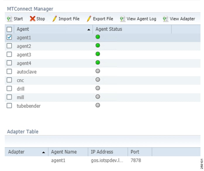
Managing Agents using SSH
The MTConnect application supports SSH and the user can login using the credentials root/C!sco123. As can be seen from the log below, the dir agent1 represents one of the four agents running and the files in that dir can be changed as needed.
Scale Validation
This section provides some scale results performed on an IC3000 showing an MTConnect Agent application running on a device using all of its memory and CPU resources for the purpose of this testing. Testing was done with traffic simulation under controlled environment to be able to scale the number of tags per second and the number of agents within the app (which would translate to number of machines) a single device can handle traffic from.
IC3000 test conditions:
■![]() Image: Version: 1.0.1, Platform ID: IC3000-2C2F-K9, HW ID: FCH2302Y003 (1.4 MTConnect)
Image: Version: 1.0.1, Platform ID: IC3000-2C2F-K9, HW ID: FCH2302Y003 (1.4 MTConnect)
■![]() MTConnect agent container is provisioned with max CPU resources available: 9000 CPU and 6000 MB RAM.
MTConnect agent container is provisioned with max CPU resources available: 9000 CPU and 6000 MB RAM.
■![]() All agents were added to EFM in streaming mode.
All agents were added to EFM in streaming mode.
■![]() Each agent used in test has four devices (machines). Each device has 71 data items, so 284 data items per agent.
Each agent used in test has four devices (machines). Each device has 71 data items, so 284 data items per agent.
| tags/sec/machine | total tags/sec | mem (mb) | cpu used |
|---|---|---|---|
| 14 | 112 | 838 | 35% |
| 30 | 240 | 1037 | 37% |
| 43 | 344 | 1057 | 39% |
| 62 | 500 | 1062 | 41% |
| 125 | 1024 | 1057 | 45% |
| tags/sec/machine | total tags/sec | mem (mb) | cpu used |
|---|---|---|---|
| 14 | 168 | 840 | 35% |
| 30 | 360 | 1152 | 39% |
| 43 | 516 | 1170 | 41% |
| 60 | 720 | 1176 | 44% |
| 105 | 1260 | 1172 | 50% |
| tags/sec/machine | total tags/sec | mem (mb) | cpu used |
|---|---|---|---|
| 14 | 275 | 857 | 40% |
| 30 | 600 | 1382 | 41% |
| 43 | 870 | 1388 | 45% |
| 62 | 1240 | 1404 | 51% |
| 100 | 2000 | 1401 | 59% |
| tags/sec/machine | total tags/sec | mem (mb) | cpu used |
|---|---|---|---|
| 14 | 550 | 1891 | 40% |
| 30 | 1200 | 1957 | 47% |
| 40 | 1600 | 1957 | 55% |
| 55 | 2200 | 1973 | 64% |
| 74 | 2960 | 1971 | 74% |
Troubleshooting
This section goes over basic troubleshooting to follow to find the root cause of various issues.
IC3000 Reset
The rest button to the left of the management port is a multi-function button. Its behavior depends on the amount of time in seconds the button is held down. It is important to follow the guidelines below as the button will not have any effect if pressed outside these guidelines.
■![]() 10-15 seconds:
10-15 seconds:
Reboot—A normal reboot of the device equivalent to power cycle.
■![]() 30-35 seconds:
30-35 seconds:
Config-reset—Erases all the user config, including apps, and reboots the device. The device will reboot with the last software image that was running.
■![]() 60-65 seconds:
60-65 seconds:
Factory-reset—Erases everything and boots up with the factory default image (1.0.1).
IC3000 IOx Troubleshooting
There are three ways to troubleshoot and collect logs from an IC300:
■![]() Using the FND Field Device Page with the various tabs and Upload Logs mechanism.
Using the FND Field Device Page with the various tabs and Upload Logs mechanism.
Figure 92 FND Field Device Page

■![]() Using System Troubleshoot Page of the Ox Local Manager via https://IP:8443, where IP is management IP address. It is important to know that the Device Config tab below with all its settings is valid only when the device is in Developer Mode. In this mode the user can use this tab to configure the IC3000 interfaces, DNS, and NTP and perform software upgrade.
Using System Troubleshoot Page of the Ox Local Manager via https://IP:8443, where IP is management IP address. It is important to know that the Device Config tab below with all its settings is valid only when the device is in Developer Mode. In this mode the user can use this tab to configure the IC3000 interfaces, DNS, and NTP and perform software upgrade.
Figure 93 System Troubleshoot Page

■![]() Using the CLI via a serial cable connected to the console port of the IC3000; no login is required.
Using the CLI via a serial cable connected to the console port of the IC3000; no login is required.
–![]() Show version to verify software and device serial number:
Show version to verify software and device serial number:
–![]() Verify IC3000 to NTP server connectivity and clock synchronization:
Verify IC3000 to NTP server connectivity and clock synchronization:
■![]() Verify the status of IC3000 and its connectivity to FND. The bold values reflect key values to look for, including that the device is running, is in production mode, and is registered and connected to the proper FND.
Verify the status of IC3000 and its connectivity to FND. The bold values reflect key values to look for, including that the device is running, is in production mode, and is registered and connected to the proper FND.
■![]() Show iox summary or detail which provides date about the guest OS IOx status.
Show iox summary or detail which provides date about the guest OS IOx status.
Sample Machine XML File
Industrial DMZ Reference
The following sections provide design guidance for the IDMZ. Design overview and guidance is provided only as this layer was not specifically validated in this Industrial Automation CVD, though the traffic required to pass through the IDMZ such as ISE and Remote access were part of the testing. The CPwE IDMZ is at the following link:
https://www.cisco.com/c/en/us/td/docs/solutions/Verticals/CPwE/3-5-1/IDMZ/DIG/CPwE_IDMZ_CVD.html
The Industrial Zone contains all IACS network and automation equipment that is critical to controlling and monitoring plant-wide operations. Industrial security standards including IEC-62443 recommend strict separation between the Industrial zone (levels 0-3) and the Enterprise/business domain and above (Levels 4-5). This segmentation and strict policy helps to provide a secure industrial infrastructure and availability of the Industrial processes. Data though is still required to be shared between the two entities such as MES or ERP data and security networking services may be required to be managed and applied throughout the enterprise and industrial zones. A zone and infrastructure is required between the Trusted industrial zone and the untrusted Enterprise zone. The IDMZ commonly referred to as Level 3.5 provides a point of access and control for the access and exchange of data between these two entities.
The IDMZ architecture provides termination points for the Enterprise and the Industrial domain and then has various servers, applications, and security policies to broker and police communications between the two domains.
The following are key guidelines and concepts for the IDMZ:
■![]() As a best practice no direct communications should occur between the Enterprise and the Industrial Zone although in some instances this may not be possible with Enterprise systems being utilized in the Industrial Zone (ISE deployments).
As a best practice no direct communications should occur between the Enterprise and the Industrial Zone although in some instances this may not be possible with Enterprise systems being utilized in the Industrial Zone (ISE deployments).
■![]() The IDMZ needs to provide secure communications between the Enterprise and the Industrial Zone using mirrored or replicated servers and applications in the IDMZ.
The IDMZ needs to provide secure communications between the Enterprise and the Industrial Zone using mirrored or replicated servers and applications in the IDMZ.
■![]() The IDMZ provides for remote access services from the external networks into the Industrial Zone.
The IDMZ provides for remote access services from the external networks into the Industrial Zone.
■![]() The IDMZ must provide a security barrier to prevent unauthorized communications into the Industrial Zone and, therefore create security policies to explicitly allow authorized communications (ISE between Enterprise and Industrial Zone).
The IDMZ must provide a security barrier to prevent unauthorized communications into the Industrial Zone and, therefore create security policies to explicitly allow authorized communications (ISE between Enterprise and Industrial Zone).
■![]() This applies to Industrial traffic leaking into the enterprise too; no IACS traffic will pass directly through the IDMZ (Controller, I/O traffic).
This applies to Industrial traffic leaking into the enterprise too; no IACS traffic will pass directly through the IDMZ (Controller, I/O traffic).
Figure 94 Industrial DMZ Reference
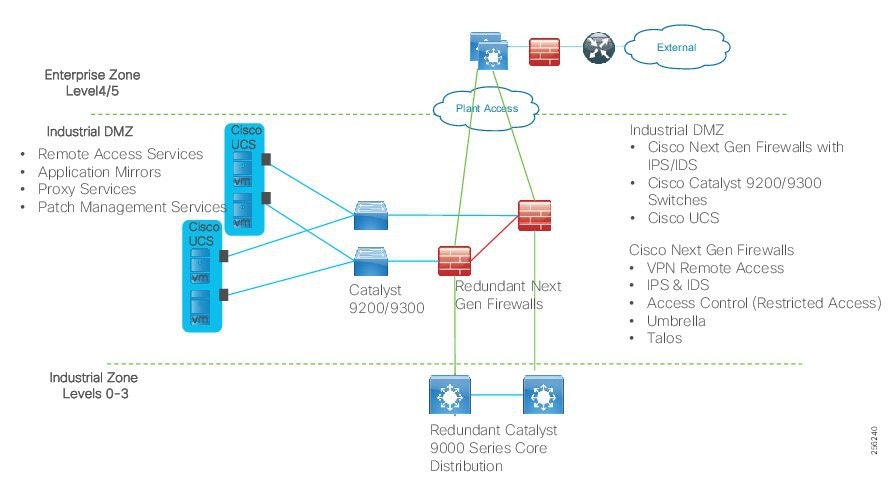
The reference design above provides a view into the components and architecture. The Redundant Firewalls are deployed to inspect and control as it enters or exits the IDMZ. Cisco Catalyst servers are deployed within the IDMZ to provide network access for UCS servers hosting the application mirrors and IDMZ services. The firewalls will run Layer 3 to both the enterprise Zone and the IDMZ. Figure 94 re-iterates the concepts of traffic flow through a DMZ related to an industrial facility.
IDMZ Industrial Characteristics and Design Considerations
The majority of industrial plant facilities have a very different physical environment at this layer of the architecture compared to the Cell/Area Zone Level 2 and below. The networking characteristics are less intensive with respect to realtime performance and equipment is physically situated in an environmentally controlled area, cabinet or room.
The following highlight the key design considerations for the IDMZ which impact platform selection, network topology, security implementation, and overall design:
■![]() Industrial Characteristics-Environmental conditions, plant layout, and cabling costs all impact the platform choices and network topology in the design. The general location and management strategy changes at Level 3 and Level 3.5 even more so. The networking platforms and servers housing the applications to support the plant are usually housed in environmentally controlled areas rather than the plant floor. The IDMZ would typically be led from a management perspective by security architects and IT professionals with considerations and requirements taken from OT as to the types of traffic required to traverse between the Enterprise and the Industrial Zones. This changes the dynamic of the platform choice which aligns with that of the traditional IT platforms. These platforms include IT based Next Generation Firewalls such as the ASA and the Cisco Firepower Threat Defense (FTD) firewalls, Cisco Catalyst 9300/Cisco Catalyst 9200 products and Cisco non-hardened UCS platforms housing the patch management, Remote access, and mirror servers.
Industrial Characteristics-Environmental conditions, plant layout, and cabling costs all impact the platform choices and network topology in the design. The general location and management strategy changes at Level 3 and Level 3.5 even more so. The networking platforms and servers housing the applications to support the plant are usually housed in environmentally controlled areas rather than the plant floor. The IDMZ would typically be led from a management perspective by security architects and IT professionals with considerations and requirements taken from OT as to the types of traffic required to traverse between the Enterprise and the Industrial Zones. This changes the dynamic of the platform choice which aligns with that of the traditional IT platforms. These platforms include IT based Next Generation Firewalls such as the ASA and the Cisco Firepower Threat Defense (FTD) firewalls, Cisco Catalyst 9300/Cisco Catalyst 9200 products and Cisco non-hardened UCS platforms housing the patch management, Remote access, and mirror servers.
■![]() Interoperability and Interconnectivity- The IDMZ is the one and only communications interface between the Industrial Zone and the Enterprise Zone. The IDMZ allows interconnectivity but will strictly control and restrict the traffic flow as well as security functions such as remote access and IACS application mirrored services. Layer 3 is required to be enabled between the IDMZ and the enterprise and the IDMZ and the Industrial Zone.
Interoperability and Interconnectivity- The IDMZ is the one and only communications interface between the Industrial Zone and the Enterprise Zone. The IDMZ allows interconnectivity but will strictly control and restrict the traffic flow as well as security functions such as remote access and IACS application mirrored services. Layer 3 is required to be enabled between the IDMZ and the enterprise and the IDMZ and the Industrial Zone.
■![]() Real-time communications, Determinism, and Performance-Packet delay and jitter within an IACS network can have significant impact on the underlying industrial process, however at the IDMZ this requirement is very different to that of the Cell/Area Zone. The general performance criteria is less sensitive to packet delay, latency, and jitter as the majority traffic flows between the Enterprise and the Industrial Zone through the IDMZ are non-real time from an industrial application perspective, and at best are near real-time.
Real-time communications, Determinism, and Performance-Packet delay and jitter within an IACS network can have significant impact on the underlying industrial process, however at the IDMZ this requirement is very different to that of the Cell/Area Zone. The general performance criteria is less sensitive to packet delay, latency, and jitter as the majority traffic flows between the Enterprise and the Industrial Zone through the IDMZ are non-real time from an industrial application perspective, and at best are near real-time.
■![]() Availability-A key metric within industrial automation is overall equipment effectiveness (OEE). Availability is still a critical requirement of the network at the IDMZ. However, if the IDMZ were to fail, the operations and processes running in the Industrial Zone and more critically the Cell/Area Zone must continue to function. Therefore, there is no dependency on the processes related to the production environment in the Industrial Zone with the applications or systems in the Enterprise Zone. Industrial Automation promotes resiliency and availability in the IDMZ with redundant servers, firewalls, Ethernet links, etc, though in smaller plant environments this may not be applied.
Availability-A key metric within industrial automation is overall equipment effectiveness (OEE). Availability is still a critical requirement of the network at the IDMZ. However, if the IDMZ were to fail, the operations and processes running in the Industrial Zone and more critically the Cell/Area Zone must continue to function. Therefore, there is no dependency on the processes related to the production environment in the Industrial Zone with the applications or systems in the Enterprise Zone. Industrial Automation promotes resiliency and availability in the IDMZ with redundant servers, firewalls, Ethernet links, etc, though in smaller plant environments this may not be applied.
■![]() Security-Security, safety, and availability are tightly aligned within an industrial security framework. When discussing industrial network security, customers are concerned with how to keep the environment safe and operational. It is recommended to follow an architectural approach to securing the control system and process domain. Recommended models would be the Purdue Model of Control Hierarchy, International Society of Automation 95 (ISA95) and IEC 62443, NIST 800-82 and NERC CIP for utility substations. The IDMZ is the key security segmentation layer between the Enterprise and the Industrial Zones. Security concepts and features are designed and implemented to provide an interface into the Industrial Zone for the business domain to support production visibility, interfaces for IACS application functions, as well as support networking and security services provided by the enterprise into the Industrial Zone. Functional sub-zones within the IDMZ are configured to segment access to IACS data and network services (for example, IT, Operations and Trusted Partner zones). The nature of firewalls at this layer provides functionality to provide enhanced security measures with the Next Generation firewalls such as Intrusion Prevention and Detection (IPS/IDS) malware detection, content security for data traversing or entering the IDMZ, and Controlled VPN termination for remote access.
Security-Security, safety, and availability are tightly aligned within an industrial security framework. When discussing industrial network security, customers are concerned with how to keep the environment safe and operational. It is recommended to follow an architectural approach to securing the control system and process domain. Recommended models would be the Purdue Model of Control Hierarchy, International Society of Automation 95 (ISA95) and IEC 62443, NIST 800-82 and NERC CIP for utility substations. The IDMZ is the key security segmentation layer between the Enterprise and the Industrial Zones. Security concepts and features are designed and implemented to provide an interface into the Industrial Zone for the business domain to support production visibility, interfaces for IACS application functions, as well as support networking and security services provided by the enterprise into the Industrial Zone. Functional sub-zones within the IDMZ are configured to segment access to IACS data and network services (for example, IT, Operations and Trusted Partner zones). The nature of firewalls at this layer provides functionality to provide enhanced security measures with the Next Generation firewalls such as Intrusion Prevention and Detection (IPS/IDS) malware detection, content security for data traversing or entering the IDMZ, and Controlled VPN termination for remote access.
■![]() Management- Within the Industrial Zone and Site Operations and Control layer there needs to be a consistent management strategy. This collaboration needs to extend into supporting the design and best practices for the IDMZ too. Where the Cell/Area Zone was operationally focused with a mixture of OT and IT personae, and the operations and control level zone was led by IT and OT personae with assistance from security architects, the IDMZ management and design will be led by IT security architects in collaboration with OT and IT engineers.
Management- Within the Industrial Zone and Site Operations and Control layer there needs to be a consistent management strategy. This collaboration needs to extend into supporting the design and best practices for the IDMZ too. Where the Cell/Area Zone was operationally focused with a mixture of OT and IT personae, and the operations and control level zone was led by IT and OT personae with assistance from security architects, the IDMZ management and design will be led by IT security architects in collaboration with OT and IT engineers.
IDMZ Firewalls
Cisco ASA with FirePOWER Services brings distinctive threat-focused next-generation security services to the Cisco ASA 5500-X Series Next-Generation Firewalls. It provides comprehensive protection from known and advanced threats, including protection against targeted and persistent malware attacks (Figure 95). Cisco ASA is the world's most widely deployed, enterprise-class stateful firewall. Cisco ASA with FirePOWER Services features these comprehensive capabilities:
■![]() Site-to-site and remote access VPN and advanced clustering provide highly secure, high-performance access and high availability to help ensure business continuity.
Site-to-site and remote access VPN and advanced clustering provide highly secure, high-performance access and high availability to help ensure business continuity.
■![]() Granular Application Visibility and Control (AVC) supports more than 4,000 application-layer and risk-based controls that can launch tailored intrusion prevention system (IPS) threat detection policies to optimize security effectiveness.
Granular Application Visibility and Control (AVC) supports more than 4,000 application-layer and risk-based controls that can launch tailored intrusion prevention system (IPS) threat detection policies to optimize security effectiveness.
■![]() The industry-leading Cisco ASA with FirePOWER next-generation IPS (NGIPS) provides highly effective threat prevention and full contextual awareness of users, infrastructure, applications, and content to detect multivector threats and automate defense response.
The industry-leading Cisco ASA with FirePOWER next-generation IPS (NGIPS) provides highly effective threat prevention and full contextual awareness of users, infrastructure, applications, and content to detect multivector threats and automate defense response.
■![]() Reputation- and category-based URL filtering offer comprehensive alerting and control over suspicious web traffic and enforce policies on hundreds of millions of URLs in more than 80 categories.
Reputation- and category-based URL filtering offer comprehensive alerting and control over suspicious web traffic and enforce policies on hundreds of millions of URLs in more than 80 categories.
■![]() AMP provides industry-leading breach detection effectiveness, sandboxing, a low total cost of ownership, and superior protection value that helps you discover, understand, and stop malware and emerging threats missed by other security layers.
AMP provides industry-leading breach detection effectiveness, sandboxing, a low total cost of ownership, and superior protection value that helps you discover, understand, and stop malware and emerging threats missed by other security layers.
Figure 95 Cisco Collective Security
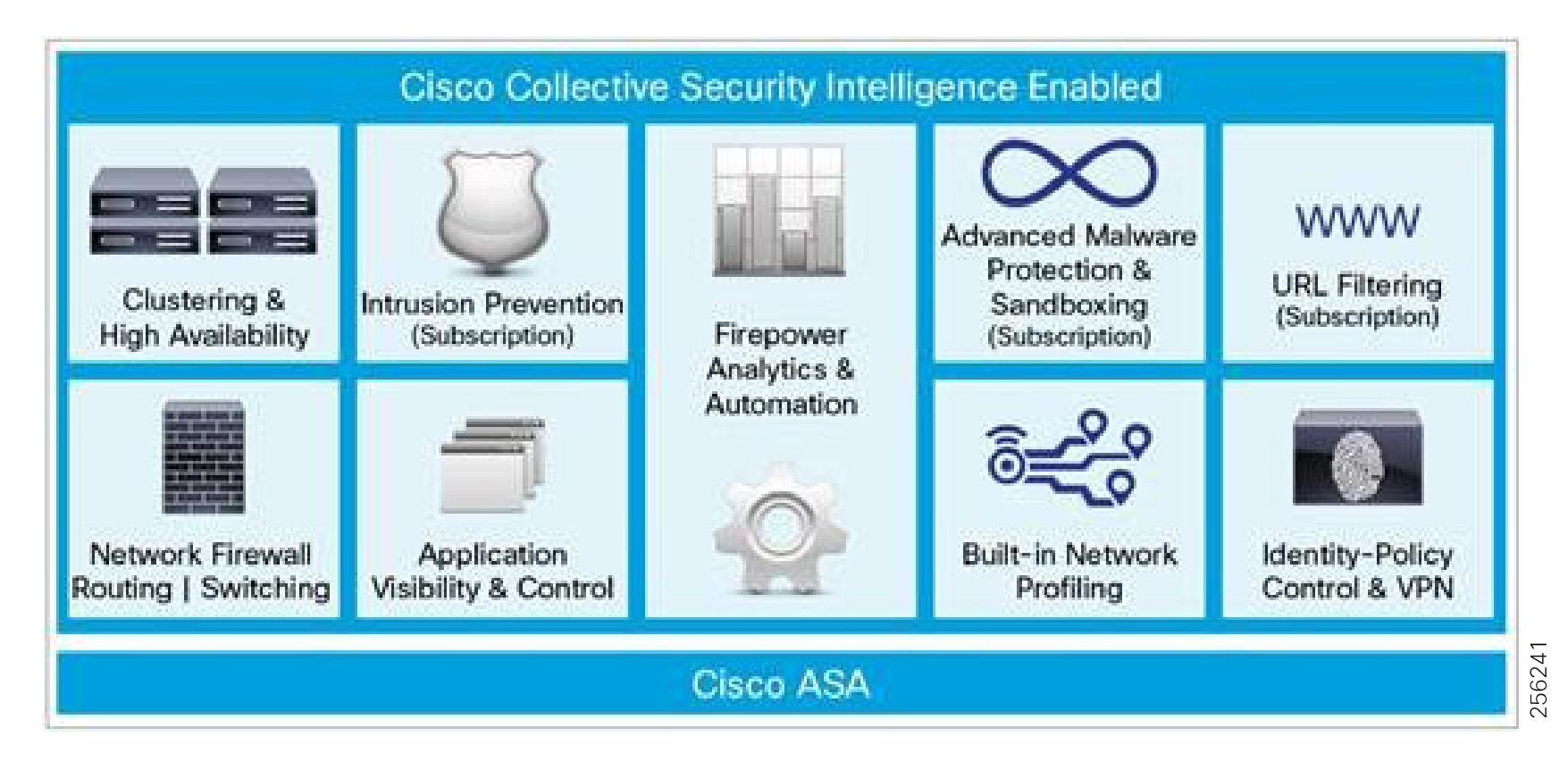
For additional details about Next Generation firewalls see:
https://www.cisco.com/c/en/us/products/collateral/security/asa-5500-series-next-generation-firewalls/datasheet-c78-733916.html?cachemode=refresh
IDMZ Data and Information Exchange
At a high level the following are the types of services that would be hosted in the IDMZ to help facilitate secure passing of IACS data and communications between the industrial zone and the Enterprise zone. The promotion of no direct access permitted between the Enterprise Zone and the Industrial zone highlights the requirement for the deployment of servers or services deployed in the IDMZ to broker communications or act as a landing pad for services between the two zones.
■![]() IACS replicated or Mirrored Data Services—As explained previously, the differing security methodologies and requirements between the enterprise and industrial zone promote the use of a DMZ, though to provide greater business agility and business intelligence data needs to be shared between the industrial zone and the enterprise zone. The DMZ will deploy servers, applications, or services to securely replicate or mirror data from the industrial zone to the enterprise zone. Depending on the IACS vendor these servers or technologies to replicate the data may be different, but the principles and functions of operation remain the same.
IACS replicated or Mirrored Data Services—As explained previously, the differing security methodologies and requirements between the enterprise and industrial zone promote the use of a DMZ, though to provide greater business agility and business intelligence data needs to be shared between the industrial zone and the enterprise zone. The DMZ will deploy servers, applications, or services to securely replicate or mirror data from the industrial zone to the enterprise zone. Depending on the IACS vendor these servers or technologies to replicate the data may be different, but the principles and functions of operation remain the same.
■![]() Secure File Transfer Services—Updates to security patches or software installation files for installation onto assets in the industrial domain are examples of files that need to be brought securely from the enterprise zone into the Industrial zone. In order to achieve this in a secure fashion and keep the premise of no direct communication, a secure file server and patch management server are deployed to provide a landing pad in the IDMZ. Files would be downloaded to the IDMZ and then could be passed to the Industrial file server situated in the Industrial zone.
Secure File Transfer Services—Updates to security patches or software installation files for installation onto assets in the industrial domain are examples of files that need to be brought securely from the enterprise zone into the Industrial zone. In order to achieve this in a secure fashion and keep the premise of no direct communication, a secure file server and patch management server are deployed to provide a landing pad in the IDMZ. Files would be downloaded to the IDMZ and then could be passed to the Industrial file server situated in the Industrial zone.
■![]() Remote Access Services—Secure remote access can provide an authorized user a real-time view of a process or industrial assets in the industrial zone. A remote access server such as a windows Remote desktop gateway can be deployed in the IDMZ. Remote Users would access this server and then remote access to authorized assets in the Industrial Zone.
Remote Access Services—Secure remote access can provide an authorized user a real-time view of a process or industrial assets in the industrial zone. A remote access server such as a windows Remote desktop gateway can be deployed in the IDMZ. Remote Users would access this server and then remote access to authorized assets in the Industrial Zone.
Security Policy Exceptions—Within Securely Traversing IACS Data Across the Industrial Demilitarized Zone Design and Implementation Guide there were some use cases where direct access was permitted between the enterprise and the industrial zone. Specific ports and guidance for deployment are highlighted in this DIG. This though is a risk acceptance that each customer should consider. Some risk may be acceptable based on lower cost of implementation and support or better performance of the application deployed.
IDMZ Data Flows Overview
Security Policy Exceptions—Within Securely Traversing IACS Data Across the Industrial Demilitarized Zone Design and Implementation Guide there were some use cases where direct access was permitted between the enterprise and the industrial zone. Specific ports and guidance for deployment is highlighted in this design guide (see link below). This though is a risk acceptance that each customer should consider. Some risk may be acceptable based on lower cost of implementation and support or better performance of the application deployed. The ISE deployment though is bound by the implementation of synchronization. An ISE Policy Service Node (PSN) must synchronize with the Policy Admin Node. In the model today, this Admin node is in the Enterprise and there is not a proxy or mirrored service function for this service. Therefore, ISE will pass directly through the firewalls at the IDMZ. The following provides a high-level view of data flows traversing between the Industrial Zone and the Enterprise Zone.
The following use cases were validated in the Securely Traversing IACS Data Across the Industrial Demilitarized Zone Design and Implementation Guide. Detailed design guidance and implementation are given in this document:
https://www.cisco.com/c/en/us/td/docs/solutions/Verticals/CPwE/3-5-1/IDMZ/DIG/CPwE_IDMZ_CVD.html
■![]() Remote Access
Remote Access
■![]() IACS Applications (Historians)
IACS Applications (Historians)
■![]() Secure File Transfer
Secure File Transfer
■![]() Active Directory Services
Active Directory Services
■![]() Certificate Services
Certificate Services
■![]() Network Time Protocol (NTP)
Network Time Protocol (NTP)
■![]() Identity Services
Identity Services
■![]() WLAN Personnel Access
WLAN Personnel Access
High Availability
Availability is still a critical requirement of the network at the IDMZ. However, if the IDMZ was to fail the operations and processes running in the Industrial Zone and more critically the Cell Area zone must continue to function. Therefore, there is no dependency on the processes related to the production environment in the Industrial Zone with the applications or systems in the Enterprise Zone. The design guidance for availability is as follows.
Firewall Resiliency
■![]() Deploy Redundant Firewalls and configure Active/Standby failover mode with a single security context.
Deploy Redundant Firewalls and configure Active/Standby failover mode with a single security context.
■![]() Use Stateful Failover configuration with a dedicated interface each of the failover link and the stateful Failover link.
Use Stateful Failover configuration with a dedicated interface each of the failover link and the stateful Failover link.
■![]() Encrypt failover communication with a failover key.
Encrypt failover communication with a failover key.
■![]() EtherChannels on the active and standby units to connect to redundant switches
EtherChannels on the active and standby units to connect to redundant switches
■![]() Configure Layer 3 Routing to communicate between the Enterprise Zones.
Configure Layer 3 Routing to communicate between the Enterprise Zones.
IDMZ Network Availability
■![]() Layer 3 routing between the IDMZ and the core/distribution routers and the IDMZ and the enterprise
Layer 3 routing between the IDMZ and the core/distribution routers and the IDMZ and the enterprise
■![]() Redundant Links throughout the architecture
Redundant Links throughout the architecture
■![]() Configuration Backups of all networking devices and firewalls
Configuration Backups of all networking devices and firewalls
■![]() Network Hardening best practices to protect the Management, Control, and Data planes of the network infrastructure
Network Hardening best practices to protect the Management, Control, and Data planes of the network infrastructure
■![]() Dual Layer 2 switches deployed for the server switch connectivity
Dual Layer 2 switches deployed for the server switch connectivity
■![]() Dual NIC connectivity from the physical servers to the redundant switches. Dual NIC technologies from the Virtual servers.
Dual NIC connectivity from the physical servers to the redundant switches. Dual NIC technologies from the Virtual servers.
■![]() Server, Virtual Server, or application redundancy where required
Server, Virtual Server, or application redundancy where required
Security
■![]() IDMZ VLAN segmentation—VLAN segmentation, as explained earlier, is a common component in the security framework to assist with isolating services in the IACS level 3 servers This should be implemented in the IDMZ architecture too. In creating several VLANs within the IDMZ and DSS environment, the servers can be isolated so that, if compromised, the servers within the VLAN container can be restricted from impacting other servers within the IDMZ.
IDMZ VLAN segmentation—VLAN segmentation, as explained earlier, is a common component in the security framework to assist with isolating services in the IACS level 3 servers This should be implemented in the IDMZ architecture too. In creating several VLANs within the IDMZ and DSS environment, the servers can be isolated so that, if compromised, the servers within the VLAN container can be restricted from impacting other servers within the IDMZ.
■![]() Policy enforcement using the Cisco Next Generations Firewall
Policy enforcement using the Cisco Next Generations Firewall
■![]() Visibility with NetFlow and Stealthwatch-The Cisco Catalyst 9000 series supports NetFlow. Enabling NetFlow on all the NetFlow capable switches in IDMZ in alignment with the level 3, Core, Distribution, and the Industrial Data center and exporting to Steathwatch will provide a plantwide view of application and network traffic. This can be used to help provide a baseline traffic profile and used to help identify anomalies in the network data flows.
Visibility with NetFlow and Stealthwatch-The Cisco Catalyst 9000 series supports NetFlow. Enabling NetFlow on all the NetFlow capable switches in IDMZ in alignment with the level 3, Core, Distribution, and the Industrial Data center and exporting to Steathwatch will provide a plantwide view of application and network traffic. This can be used to help provide a baseline traffic profile and used to help identify anomalies in the network data flows.
■![]() Enhanced NGN features:
Enhanced NGN features:
–![]() IPS/IDS can be deployed at the IP NGN firewalls for any traffic traversing the IDMZ.
IPS/IDS can be deployed at the IP NGN firewalls for any traffic traversing the IDMZ.
–![]() Anomaly malware detection can be deployed to inspect any files traversing the firewall.
Anomaly malware detection can be deployed to inspect any files traversing the firewall.
For more information about Next Generation firewalls see:
https://www.cisco.com/c/en/us/products/collateral/security/asa-5500-series-next-generation-firewalls/datasheet-c78-733916.html?cachemode=refresh
Availability
This section describes the resiliency options validated for Industrial Automation at the distribution switch and the Cell/Area Zone.
Distribution Switch Resiliency
Cisco StackWise—480
The Cisco Catalyst 3850 and Cisco Catalyst 9300 support StackWise-480 configurations to provide platform resiliency at the distribution layer. A switch stack can have up to eight stacking-capable switches connected through their StackWise-480 ports. The stack members work together as a unified system. Layer 2 and Layer 3 protocols present the entire switch stack as a single entity to the network.
A switch stack always has one active switch and one standby switch. The active switch will provide control of the management plane for the stack. If the active switch becomes unavailable, the standby switch assumes the role of the active switch and continues to the keep the stack operational. In this guide, the switch stacks were validated with two switches to provide the Cell/Area Zone distribution switch resiliency.
The active switch has the saved and running configuration file for the switch stack. The standby switch automatically receives the synchronized running configuration file. Stack members receive synchronized copies when the running configuration file is saved into the startup configuration file. If the active switch becomes unavailable, the standby switch takes over with the current running configuration.
Configuring Cisco StackWise
Stack Member Priority
A higher priority value for a stack member increases the probability of it being elected active switch and retaining its stack member number. The priority value can be 1 to 15. The default priority value is 1. You can display the stack member priority value by using the show switch EXEC command.
We recommend assigning the highest priority value to the switch that you prefer to be the active switch. This ensures that the switch is reelected as the active switch if a reelection occurs.
To change the priority value for a stack member, use the following command:
For example:
The new priority value takes effect immediately but does not affect the current active switch. The new priority value helps determine which stack member is elected as the new active switch when the current active switch or the switch stack resets.
Stack MAC Address Persistence
A switch stack is identified in the network by its bridge ID and, if it is operating as a Layer 3 device, its router MAC address. The bridge ID and router MAC address are determined by the MAC address of the active switch. If the active switch changes, the MAC address of the new active switch determines the new bridge ID and router MAC address. The default behavior could cause traffic disruption due to the new MAC address being learned in the network. To avoid this situation, configure stack MAC persistency so that the stack MAC address never changes to the new active switch MAC address.
To configure use the following command:
Stack Member Renumbering
The stack member number (1 to 9) identifies each member in the switch stack. The member number also determines the interface-level configuration that a stack member uses. You can display the stack member number by using the show switch EXEC command:
A new, out-of-the-box switch (one that has not joined a switch stack or has not been manually assigned a stack member number) ships with a default stack member number of 1. When it joins a switch stack, its default stack member number changes to the lowest available member number in the stack.
Stack members in the same switch stack cannot have the same stack member number. Every stack member, including a standalone switch, retains its member number until you manually change the number or unless the number is already being used by another member in the stack.
It is possible to manually change the stack member number by configuring:
The new number goes into effect after that stack member resets (or after you use the reload slot stack-member-number privileged EXEC command) and only if that number is not already assigned to any other members in the stack.
For more information on the Cisco Catalyst 3850 StackWise—480 configuration, see:
■![]() For Cisco Catalyst 3850:
For Cisco Catalyst 3850:
https://www.cisco.com/c/en/us/td/docs/switches/lan/catalyst3850/software/release/3se/ha_stack_manager/configuration_guide/b_hastck_3se_3850_cg/b_hastck_3se_3850_cg_chapter_010.html#reference_5415C09868764F0FA05F88897F108139
■![]() For Cisco Catalyst 9300:
For Cisco Catalyst 9300:
https://www.cisco.com/c/en/us/td/docs/switches/lan/catalyst9300/software/release/16-5/configuration_guide/stck_mgr_ha/b_165_stck_mgr_ha_9300_cg/managing_switch_stacks.html
Troubleshooting Cisco StackWise
The following show commands provide information about the stack.
| | |
| | ■ ■ ■ ■ |
| | |
| | |
| | |
| | |
| | |
| | |
Hot Standby Router Protocol
Hot Standby Router Protocol (HSRP) is another redundancy option that enables multiple switches to work in conjunction to provide distribution services. The standby ip interface configuration command activates HSRP on the configured interface. If an IP address is specified, that address is used as the designated address for the Hot Standby group. If no IP address is specified, the address is learned through the standby function. You must configure at least one Layer 3 port on the LAN with the designated address. Configuring an IP address always overrides another designated address currently in use. It is recommended to configure the lowest IP in the network as standby IP to guarantee that the primary router will become the Internet Group Management Protocol (IGMP) snooping querier.
In the recommended implementation, HSRP is configured in a Switch Virtual Interface (SVI). To configure HSRP, assign a virtual IP and group number to the interface. The following is an example of HSRP configuration in primary peer:
The following is an example of the standby peer:
Note that virtual IP is the same while physical IP varies per peer.
Configuring HSRP Priority
Assigning a priority allows you to select the active and standby routers. If preemption is enabled, the router with the highest priority becomes the active router again after recovering from a failure. If priorities are equal, the current active router does not change. The highest number (1 to 255) represents the highest priority (most likely to become the active router).
When routing is first enabled for the interface, it does not have a complete routing table. If it is configured to preempt, it becomes the active router, even though it is unable to provide adequate routing services. To solve this problem, configure a delay time to allow the router to update its routing table.
To configure priority in the desired active peer, add this line to the interface configuration (since default priority is 100, the configured number should be higher):
Configuring Preemption
When the local router has a higher priority than the active router, it assumes control as the active router. As an option a delay can be configured, which will cause the local router to postpone taking over the active role for the number of seconds shown:
HSRP Timers
HSRP uses two timers: hello interval and hold time. The hello interval defines the frequency that hello packets are sent to the other peer. Hold time indicates the amount of time to wait before marking the peer as down. The hold time should be three or more times greater than the hello interval. The values used in the following example were used during validation to provide faster convergence than the default values. To configure those timers:
Troubleshooting HSRP
The commands show standby and show standby brief provide configuration and current status details:
If HSRP does not recognize its HSRP peers, verify physical layer connectivity and configuration.
Internet Group Management Protocol Considerations
IGMP snooping should be configured to route multicast traffic only to those hosts that request traffic from the specific multicast group. IGMP snooping is configured by default in Cisco IE switches, but IGMP snooping querier should be configured on the distribution switches using the following command:
IGMP selects the querier with the lowest IP in the network, hence the importance of configuring the HSRP IP to be the lowest in the network.
Cell/Area Zone Resiliency
EtherChannel
To configure an EtherChannel using Link Aggregation Control Protocol (LACP) in active mode between the access and distribution switches, configure a port-channel interface on each switch and then configure the links as members of the port-channel.
Figure 96 Example of EtherChannel in the Cell/Area Zone
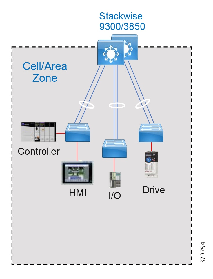
The channel-group command binds the physical port and the logical interface. The following is an example of EtherChannel configuration:
The mode active refers to the LACP negotiation state; in this mode the port is able to start negotiation with other ports sending LACP packets.
After you configure an EtherChannel, configuration changes applied to the port-channel interface apply to all the physical ports assigned to the port-channel interface. To change the parameters of all ports in an EtherChannel, apply configuration commands to the port-channel interface, for example, spanning-tree commands or commands to configure a Layer 2 EtherChannel as a trunk.
Troubleshooting EtherChannels
The show commands in Table 50 provide information about the EtherChannel.
| Command | Purpose |
|---|---|
| show etherchannel [ channel-group-number{ detail | port | port-channel | protocol |summary }] { detail | load-balance | port |port-channel | protocol | summary} | Displays EtherChannel information in a brief, detailed, and one-line summary form. Also displays the load-balance or frame-distribution scheme, port, port-channel, and protocol information. |
| show lacp [channel-group-number] {counters | internal | neighbor} | Displays LACP information such as traffic information, the internal LACP configuration, and neighbor information. |
Configure EtherChannels Using Device Manager
This section assumes that the Cisco IE switch has been installed and configured with IP address for management. For more details on setting up a Cisco IE switch, refer to the corresponding installation guides.
1. ![]() Log in to the switch using Device Manager credentials.
Log in to the switch using Device Manager credentials.
2. ![]() Go to the Configuration menu.
Go to the Configuration menu.
3. ![]() Select Interface -> Logical as shown in Figure 97.
Select Interface -> Logical as shown in Figure 97.
Figure 97 Device Manager Configuration Options
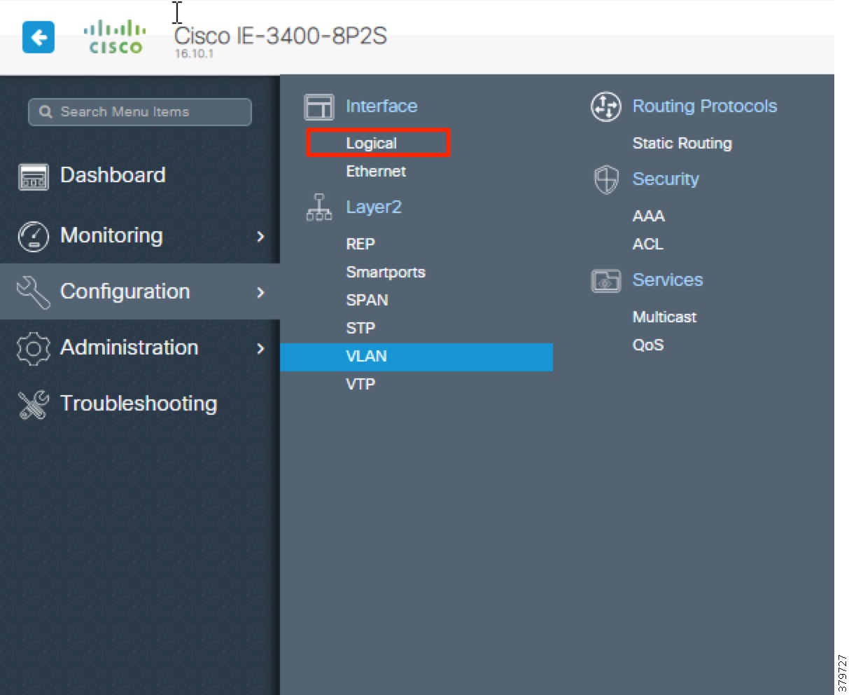
4. ![]() Fill out port channel details and associate interfaces as shown in Figure 98.
Fill out port channel details and associate interfaces as shown in Figure 98.
Figure 98 EtherChannel Configuration
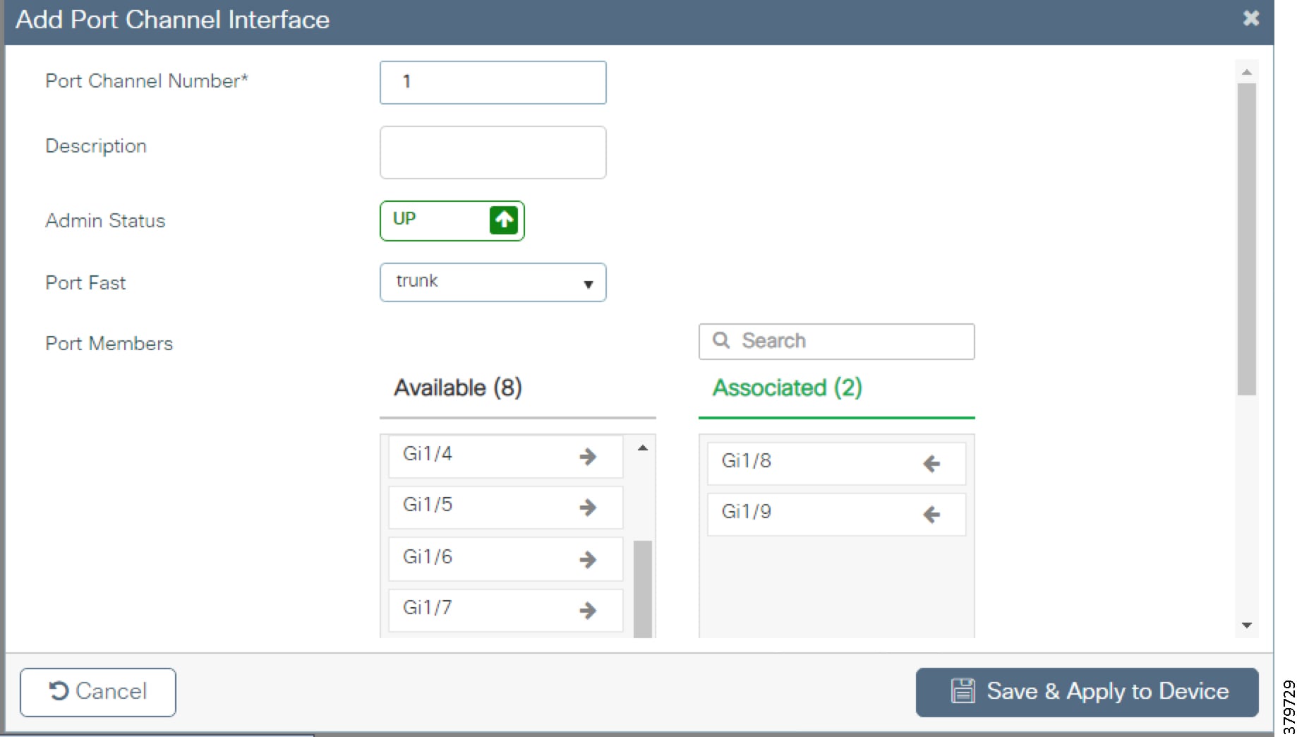
5. ![]() Click Save & Apply to Device.
Click Save & Apply to Device.
Resilient Ethernet Protocol
Resilient Ethernet Protocol (REP) is a resiliency protocol used on switch rings in the Cell/Area Zone as shown in Figure 99 or as an open segment to connect an HSR ring to the distribution as shown in Figure 100. When used on a ring, the edge ports reside on the same logical witch in the distribution. When used as an open segment, the edge ports are located on separate switches. Refer to Table 51 for edge port location used with different Distributed Layer Resiliency protocols.
| Topology | Distribution Layer Resiliency Protocol | Edge Port Location |
|---|---|---|
| REP Ring | Cisco StackWise | Edge ports should be located on the stack switch, with each edge port on different stack member. |
| REP Ring | HSRP | Both edge ports should be located on the primary HSRP distribution switch. |
| HSR Ring | Cisco StackWise or HSRP | Each edge ports should be located on access switches connected to the distribution, with only one edge per access switch |
Figure 99 REP on Cell/Area Zone Ring
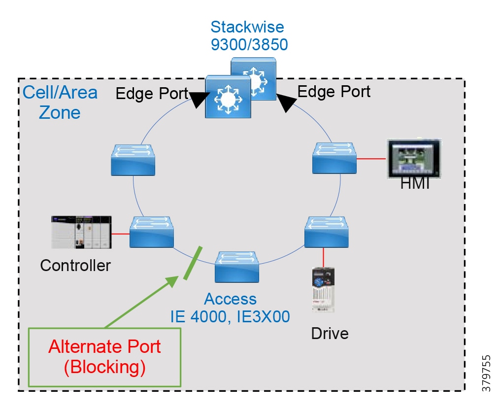
Figure 100 REP Used to Connect HSR Ring to Distribution
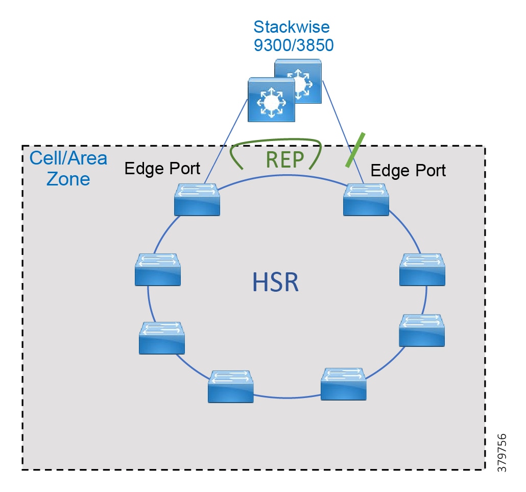
REP Guidelines
■![]() REP ports must be Layer 2 trunk ports.
REP ports must be Layer 2 trunk ports.
■![]() REP and Spanning Tree Protocol (STP) cannot run on the same segment or interface.
REP and Spanning Tree Protocol (STP) cannot run on the same segment or interface.
■![]() Begin by configuring one port at the end of the segment and then configure the contiguous ports to minimize the number of segments and the number of blocked ports.
Begin by configuring one port at the end of the segment and then configure the contiguous ports to minimize the number of segments and the number of blocked ports.
■![]() A device can have no more than two ports that belong to the same segment.
A device can have no more than two ports that belong to the same segment.
■![]() Each segment port can have only one external neighbor.
Each segment port can have only one external neighbor.
■![]() REP ports follow these rules:
REP ports follow these rules:
–![]() If only one port on a device is configured in a segment, the port should be an edge port.
If only one port on a device is configured in a segment, the port should be an edge port.
–![]() If two ports on a device belong to the same segment, both ports must be edge ports or both ports must be regular segment ports.
If two ports on a device belong to the same segment, both ports must be edge ports or both ports must be regular segment ports.
–![]() If two ports on a device belong to the same segment and one is configured as an edge port and one as a regular segment port, the no-neighbor command option must be applied on the edge port.
If two ports on a device belong to the same segment and one is configured as an edge port and one as a regular segment port, the no-neighbor command option must be applied on the edge port.
Configure Administrative VLAN
To avoid the delay introduced by relaying messages that are related to link-failures or VLAN-blocking notifications during VLAN load balancing, REP floods packets at the hardware flood layer (HFL) to a regular multicast address. These messages are flooded to the whole network and not just to the REP segment. You can control the flooding of these messages by configuring an administrative VLAN for the whole domain.
Follow these guidelines when configuring the REP administrative VLAN:
■![]() Only one administrative VLAN can exist on a switch and on a segment. However, the software does not enforce this.
Only one administrative VLAN can exist on a switch and on a segment. However, the software does not enforce this.
■![]() If you do not configure an administrative VLAN, the default is VLAN 1.
If you do not configure an administrative VLAN, the default is VLAN 1.
■![]() If you want to configure REP on an interface, ensure that the REP administrative VLAN is part of the trunk encapsulation list.
If you want to configure REP on an interface, ensure that the REP administrative VLAN is part of the trunk encapsulation list.
Configuration Commands:
Enable REP on Interfaces
For the REP operation, you must enable REP on each interface (that will be part of the segment) and identify the segment ID. This task is required and must be done before other REP configuration. You must also configure a primary and secondary edge port on each segment. All other steps are optional.
Edge Ports
To configure a port as an edge port, use the following command in interface configuration mode:
The primary keyword is optional and allows for manual selection of the primary edge. If the primary keyword is used, the other edge port becomes the secondary edge port (no keyword required). To configure the secondary edge port, omit the primary keyword:
Non-Edge Ports
To configure a port as a member of the REP segment, use the following command in interface configuration mode:
Preemption
Preemption is done either manually with the rep preempt segment < ID > command or automatically if you configure rep preempt delay seconds command for the primary edge port.
When a segment recovers after a link failure, one of the two ports adjacent to the failure comes up as the ALT port. Then, after preemption, the location of the ALT ports become the primary edge port unless additional configuration is done for load balancing and alternate port.
Example of automatic preemption:
Example of manual preemption:
Selecting an Alternate Port
It is possible to select an alternate port other than the edge port by configuring the load balancing feature on the primary edge port and specifying the alternate port using the port ID or the neighbor offset number using the following command:
Port ID
To identify the port ID of a port in the segment, enter the command:
Neighbor Offset Number
The neighbor offset number of a port in the segment identifies the downstream neighbor port of an edge port. The neighbor offset number range is -256 to 256; a value of 0 is invalid. The primary edge port has an offset number of 1; positive numbers above 1 identify downstream neighbors of the primary edge port. Negative numbers indicate the secondary edge port (offset number -1) and its downstream neighbors.
Example
The following example uses the neighbor offset number, in this case the alternate port is 7 ports downstream:
For more information, refer to Cisco Industrial Ethernet 4000, 4010, and 5000 Switch Software Configuration Guide:
https://www.cisco.com/c/en/us/td/docs/switches/lan/cisco_ie4010/software/release/15-2_4_EC/configuration/guide/scg-ie4010_5000.html
Note: When using Cisco StackWise for distribution with a REP ring, it is a good practice to locate the alternate port in between access switches to achieve higher Layer 3 convergence in case of primary stack member power failure.
Troubleshooting REP
Enter this command in order to see the status of a REP adjacency:
Use the show rep topology command on any router on the segment to see the current topology:
Configure REP Using Device Manager
This section assumes that the Cisco IE switch has been installed and configured with an IP address for management access. For more details on setting up Cisco IE switch, refer corresponding Installation Guides.
1. ![]() Log in to the switch using Device Manager credentials.
Log in to the switch using Device Manager credentials.
2. ![]() Go to the Configuration menu.
Go to the Configuration menu.
3. ![]() Select Layer 2 -> REP.
Select Layer 2 -> REP.
4. ![]() Select the Admin VLAN for the entire domain (all segments).
Select the Admin VLAN for the entire domain (all segments).
5. ![]() Click a row for an interface to bring up the Edit Rep Interface window and then click Enable to enable REP on the interface. REP is disabled by default. When enabled, the interface is a regular segment port unless it is configured as an edge port.
Click a row for an interface to bring up the Edit Rep Interface window and then click Enable to enable REP on the interface. REP is disabled by default. When enabled, the interface is a regular segment port unless it is configured as an edge port.
Figure 101 Configuring REP

6. ![]() Enter the Segment ID.
Enter the Segment ID.
7. ![]() Select the REP Port Type :
Select the REP Port Type :
■![]() Edge—A secondary edge port that participates in VLAN load balancing.
Edge—A secondary edge port that participates in VLAN load balancing.
■![]() Edge no-neighbor—A secondary edge port that is connected to a non-REP switch.
Edge no-neighbor—A secondary edge port that is connected to a non-REP switch.
■![]() Preferred—A secondary edge port that is the preferred alternate port for VLAN load balancing.
Preferred—A secondary edge port that is the preferred alternate port for VLAN load balancing.
■![]() Edge no-neighbor preferred—A secondary edge port that is connected to a non-REP switch and is the preferred port for VLAN load balancing.
Edge no-neighbor preferred—A secondary edge port that is connected to a non-REP switch and is the preferred port for VLAN load balancing.
■![]() Edge no-neighbor primary—A secondary edge port that always participates in VLAN load balancing in this REP segment and is connected to a non-REP switch.
Edge no-neighbor primary—A secondary edge port that always participates in VLAN load balancing in this REP segment and is connected to a non-REP switch.
■![]() Edge no-neighbor primary preferred—An edge port that always participates in VLAN load balancing in this REP segment, is connected to a non-REP switch, and is the preferred port for VLAN load balancing.
Edge no-neighbor primary preferred—An edge port that always participates in VLAN load balancing in this REP segment, is connected to a non-REP switch, and is the preferred port for VLAN load balancing.
■![]() Edge preferred—A secondary edge port that is the preferred alternate port for VLAN load balancing.
Edge preferred—A secondary edge port that is the preferred alternate port for VLAN load balancing.
■![]() Edge primary—An edge port that always participates in VLAN load balancing in this REP segment.
Edge primary—An edge port that always participates in VLAN load balancing in this REP segment.
■![]() Edge primary preferred—An edge port that always participates in VLAN load balancing in this REP segment and is the preferred port for VLAN load balancing.
Edge primary preferred—An edge port that always participates in VLAN load balancing in this REP segment and is the preferred port for VLAN load balancing.
■![]() None—This port is not part of the REP segment. This is the default.
None—This port is not part of the REP segment. This is the default.
■![]() Transit—A non-edge port in the REP segment.
Transit—A non-edge port in the REP segment.
8. ![]() (Optional) Designate a physical interface to receive segment topology change notices (STCNs).
(Optional) Designate a physical interface to receive segment topology change notices (STCNs).
9. ![]() (Optional) Identify one or more segments to receive STCNs. Enable to enable sending STCNs to STP networks.
(Optional) Identify one or more segments to receive STCNs. Enable to enable sending STCNs to STP networks.
10. ![]() Click Update & Apply to Device.
Click Update & Apply to Device.
REP Fast
The REP Fast feature supported on the Cisco IE 3x00 switches follows the same functionality as REP but improves failure detection time among the participating switches. REP Fast can be used in conjunction with traditional REP in ring topologies to accommodate switches that do not support REP Fast.
Figure 102 REP Fast

After configuring ports for REP, any ports that will participate in REP Fast require the following command in interface configuration mode:
In addition to the show rep topology command, the following can be used to view the beacon frame count for ports participating in REP Fast:
High-Availability Seamless Redundancy
Figure 103 HSR Ring
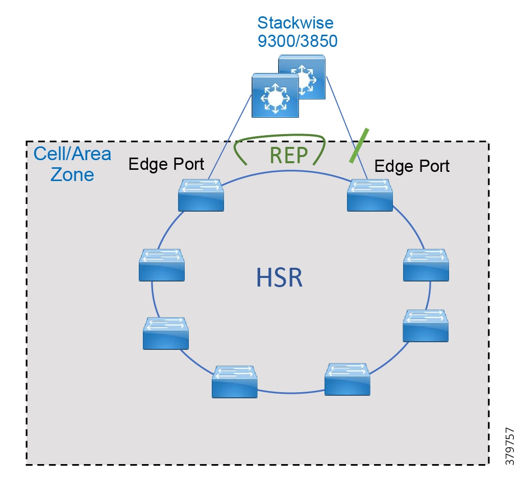
Before configuring HSR, check if HSR is enabled; newer versions have it enabled by default.
If HSR is enabled, skip this step; otherwise, use the following command to enable:
For the change to take effect, the switch must be reloaded. Confirm the reload when prompted and wait for the switch to reload and boot. Verify that the HSR feature is activated.
Ensure that the member interfaces of an HSR ring are not participating in any redundancy protocols such as FlexLinks, EtherChannel, or REP before configuring an HSR ring.
Configuring HSR
Follow these steps to configure HSR:
1. ![]() Shut down the ports before configuring the HSR ring:
Shut down the ports before configuring the HSR ring:
2. ![]() Configure switch port and VLANs as desired:
Configure switch port and VLANs as desired:
3. ![]() Disable Precision Time Protocol (PTP), which is not supported on HSR interfaces:
Disable Precision Time Protocol (PTP), which is not supported on HSR interfaces:
4. ![]() Create the HSR ring interface and assign the ports to the HSR ring. This command should be issued in the interface configuration. The two interfaces will be bundled in an HSR interface:
Create the HSR ring interface and assign the ports to the HSR ring. This command should be issued in the interface configuration. The two interfaces will be bundled in an HSR interface:
5. ![]() Turn on the HSR interface:
Turn on the HSR interface:
6. ![]() Make sure the enable DualUplinkEnhancement feature is not disabled. This feature is required to support the connectivity to a dual router (HSRP in this case) on the distribution layer.
Make sure the enable DualUplinkEnhancement feature is not disabled. This feature is required to support the connectivity to a dual router (HSRP in this case) on the distribution layer.
7. ![]() If the output shows no hsr-ring 1 fpgamode-DualUplinkEnhancement, issue the following command:
If the output shows no hsr-ring 1 fpgamode-DualUplinkEnhancement, issue the following command:
8. ![]() Follow these optional steps to configure CDP and LLDP to provide information about HSR ring nodes:
Follow these optional steps to configure CDP and LLDP to provide information about HSR ring nodes:
–![]() Enable LLDP globally:
Enable LLDP globally:
–![]() Enable LLDP on the ports to be assigned to the HSR ring:
Enable LLDP on the ports to be assigned to the HSR ring:
–![]() Enable CDP on the ports to be assigned to the HSR ring:
Enable CDP on the ports to be assigned to the HSR ring:
9. ![]() Follow these optional steps to enable HSR alarms:
Follow these optional steps to enable HSR alarms:
–![]() Enable the HSR alarm facility:
Enable the HSR alarm facility:
–![]() Enable SNMP notification for HSR alarms:
Enable SNMP notification for HSR alarms:
–![]() Associate HSR alarms with the Major Relay:
Associate HSR alarms with the Major Relay:
HSR with REP Best Practices
■![]() If REP preemption is required, it is recommended to do manual preemption to avoid an unplanned downtime. REP preemption could cause a multicast tree re-convergence that affects nodes attached to the REP segment.
If REP preemption is required, it is recommended to do manual preemption to avoid an unplanned downtime. REP preemption could cause a multicast tree re-convergence that affects nodes attached to the REP segment.
■![]() For REP segment, the edge port in the Cisco IE 4000 connected directly to HSRP subordinate should be primary so it gets blocked by default in preemption.
For REP segment, the edge port in the Cisco IE 4000 connected directly to HSRP subordinate should be primary so it gets blocked by default in preemption.
■![]() Enable bridge protocol data unit (BPDU) filtering in ports connecting to end devices and distribution on the Cisco IE 4000 participating in HSR ring to avoid ports getting into a blocked state after topology changes.
Enable bridge protocol data unit (BPDU) filtering in ports connecting to end devices and distribution on the Cisco IE 4000 participating in HSR ring to avoid ports getting into a blocked state after topology changes.
■![]() Avoid using access ports on the distribution switch for VLANs being used in the ring to avoid a HSRP split brain scenario. If connecting devices directly to the distribution switches, use a different VLAN.
Avoid using access ports on the distribution switch for VLANs being used in the ring to avoid a HSRP split brain scenario. If connecting devices directly to the distribution switches, use a different VLAN.
Troubleshooting HSR
The show commands in Table 52 can be used to troubleshoot HSR.
| Command | Purpose |
|---|---|
| show hsr ring { 1 | 2 } [ detail ] | Displays configuration details and the current state for the specified HSR ring |
| show hsr statistics | Displays statistics for HSR components. To clear HSR statistics information, enter the command clear hsr statistics. |
| show hsr node-table | Displays all MAC addresses accessible to the switch using the HSR interface, including other nodes in the ring as well as devices attached to other nodes. |
| show hsr vdan-table | Displays the HSR Virtual Doubly Attached Node (VDAN) table, which contains devices directly connected to the switch for which the switch acts as proxy. This table is also known as the Proxy node table. |
| show cdp neighbors and show lldp neighbors | Displays neighbor information for the switch, which is useful when troubleshooting connectivity issues. |
| show alarm settings | begin hsr | Displays HSR alarm configuration. |
Example of HSR Ring Detail:
| Event Number | Event Description | System Log (Level) | Alert/Alarm Log | Alarm LED and Output Relay |
|---|---|---|---|---|
| 1 | Ring goes from UP to DOWN state. | 2 | 2 | Major Alarm/Assert |
| 2 | Ring goes from DOWN to UP state. | 6 | 6 | De-assert |
| 3 | One ring port goes DOWN and the other ring port and the ring itself are UP. | 3 | 3 | |
| 4 | Both ring ports are UP again. | 6 | 6 |
HSR Events
You can view currently active alarms using the show facility alarm status command. The following example shows alarm status for minor and major HSR alarms:
Configure HSR Using Device Manager
This section assumes that the Cisco IE switch has been installed and configured with an IP Address for remote access. For more details on setting up a Cisco IE switch, refer to the corresponding installation guides.
1. ![]() Log in to the switch using Device Manager credentials.
Log in to the switch using Device Manager credentials.
Figure 104 Device Manager Login Screen
2. ![]() After a successful login, the Dashboard for the switch loads.
After a successful login, the Dashboard for the switch loads.
Figure 105 Cisco IE 4000 Device Manager Dashboard
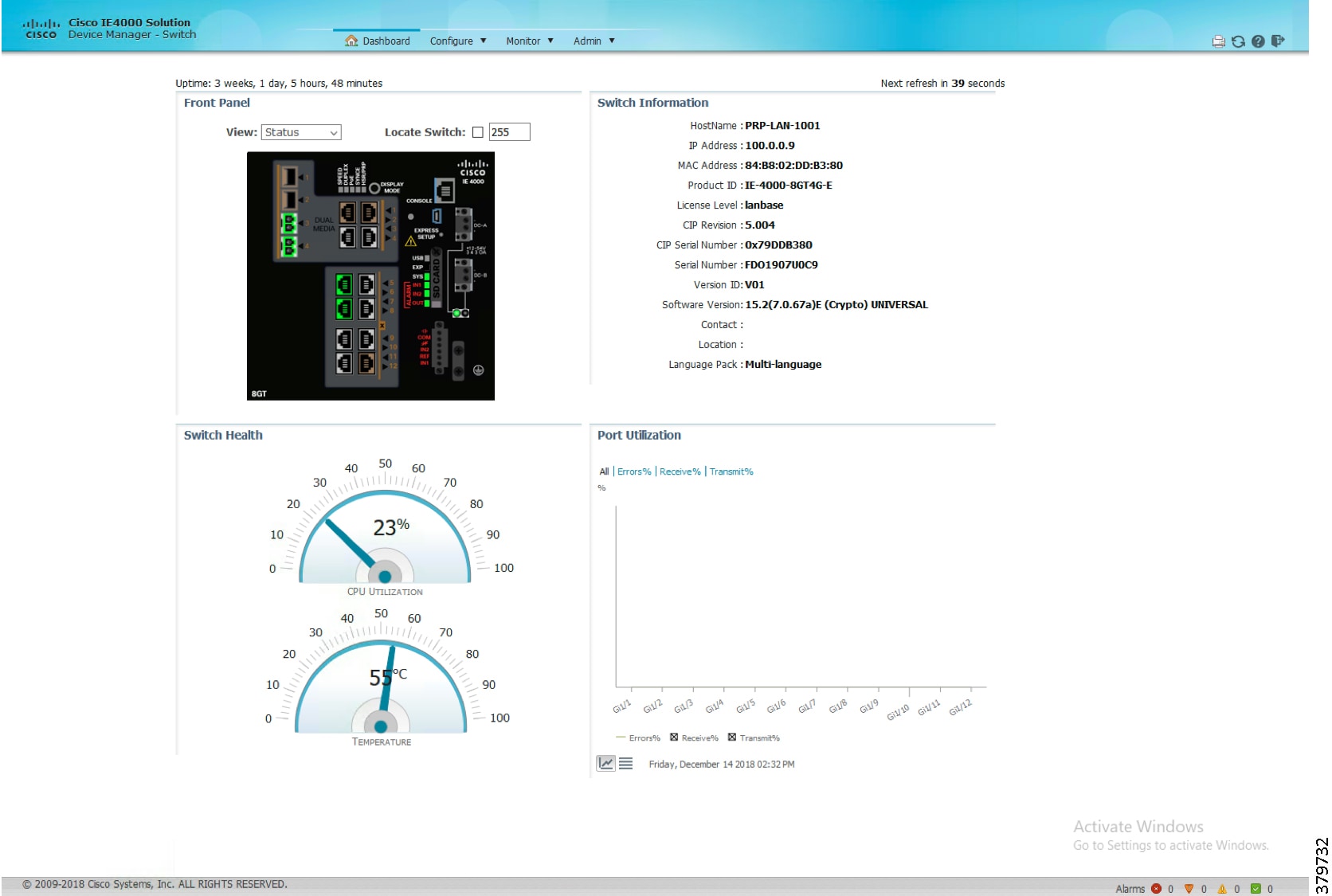
3. ![]() Enable the HSR feature on the Cisco IE switch using the options highlighted in Figure 106.
Enable the HSR feature on the Cisco IE switch using the options highlighted in Figure 106.
Figure 106 Enable HSR Feature
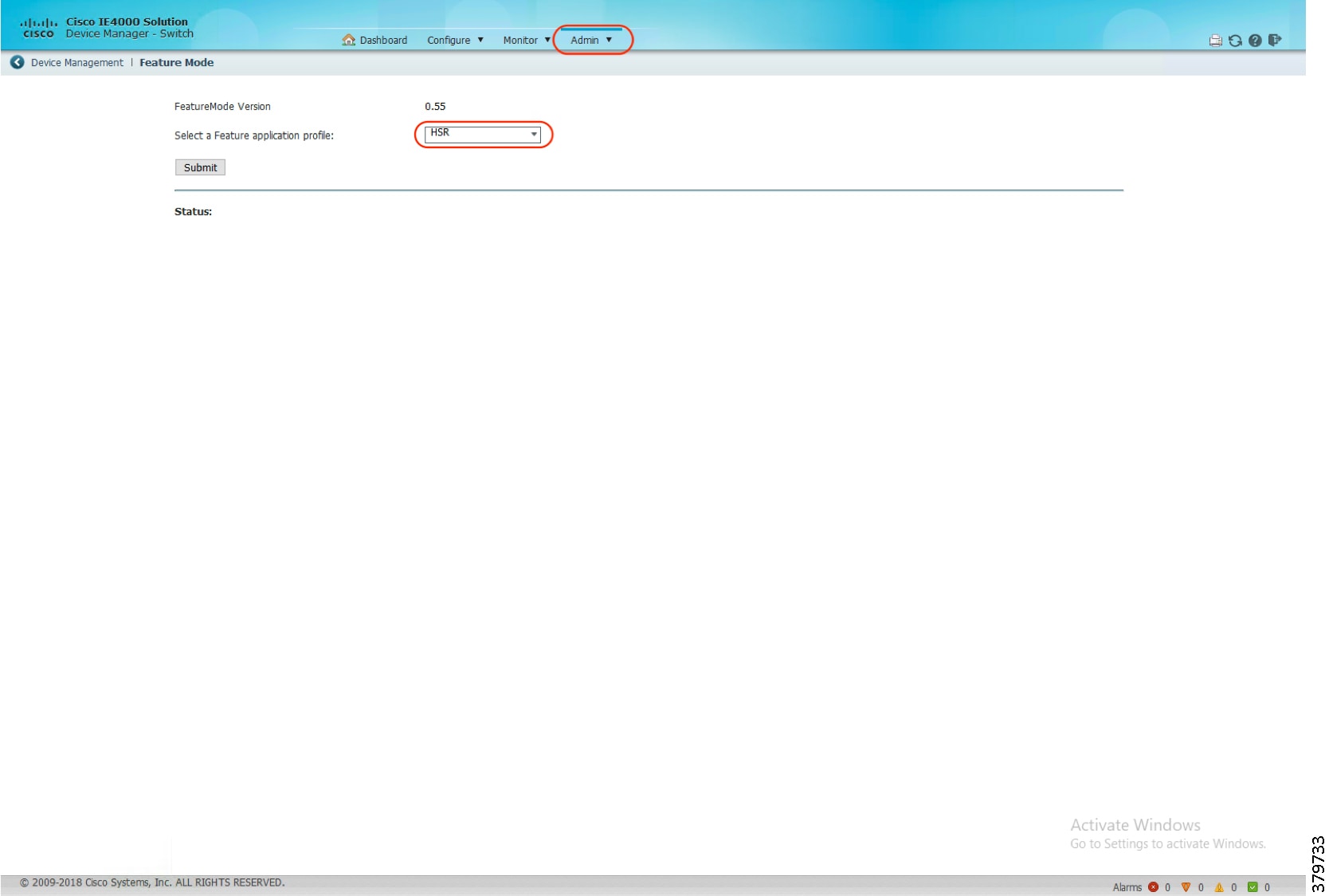
4. ![]() Configure HSR Ring and its related parameters on the Cisco IE switch using the options highlighted in Figure 107.
Configure HSR Ring and its related parameters on the Cisco IE switch using the options highlighted in Figure 107.
Figure 107 HSR Ring Parameters
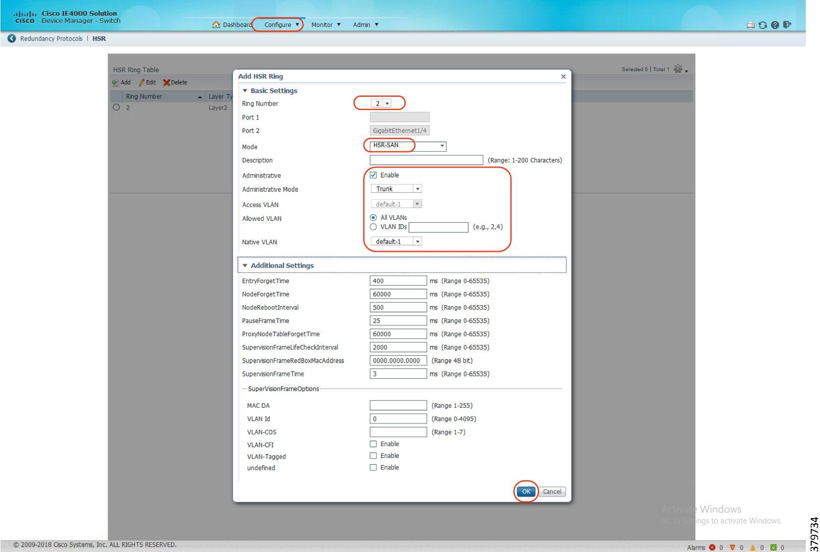
HSR-HSR
HSR rings can also be implemented in such a way that key switches are participating in two HSR rings, using four interfaces to connect the respective rings, which is known as HSR-HSR or Quadbox. When the HSR-HSR mode is licensed and enabled, the switch shuts all non-HSR ports to avoid traffic interference. Connectivity to the HSR-HSR switch can be done through the HSR-HSR ports or the out-of-band console interface.
Figure 108 HSR-HSR
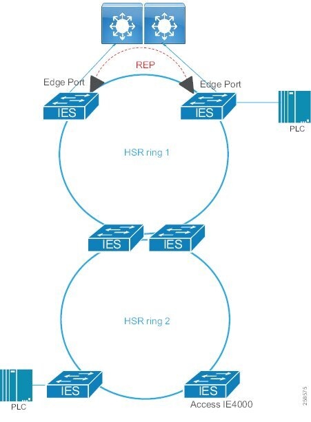
All aforementioned HSR configurations are required for all switches in the rings. For the Quadbox switches, the following additional command is required in configuration mode:
The first two gigabit interfaces will be used for HSR-ring1 and the second two gigabit interfaces will be used for HSR-ring2.
Example of HSR Ring Summary in HSR-HSR Mode:
Example of HSR Ring Detail in HSR-HSR Mode:
HSR-PRP RedBox (Dual RedBox)
A Redundancy Box (RedBox) is deployed when an end node does not support two network interfaces and PRP redundancy. The RedBox provides the DAN functionality for devices connecting to it. This is the role of the Cisco IE 4000 or Cisco IE 4010 and Cisco IE 5000 in a PRP redundancy deployment. The node behind a RedBox appears for other nodes like a DAN and is known as a Virtual DAN (VDAN).
HSR-PRP RedBox, also known as Dual RedBox, is used to connect PRP and HSR networks together. The HSR-PRP feature is supported only on the Cisco IE 4000.
A typical deployment of the HSR-PRP feature is to use two switches to connect to two different LANs, namely LAN-A and LAN-B of a PRP network and HSR network. Traffic flows between the PRP and HSR networks through RedBoxes. RedBoxes do not forward duplicate frames in the same direction to avoid loops. RedBoxes convert PRP frames to HSR frames and vice versa.
Figure 109 shows an HSR ring connected to a PRP network through two RedBoxes, one for each LAN. In this example, the source frame originates in the PRP network and reaches the destination in the HSR network. RedBoxes are configured to support PRP traffic on the interlink ports and HSR traffic on the ring ports.
Figure 109 HSR-PRP RedBox
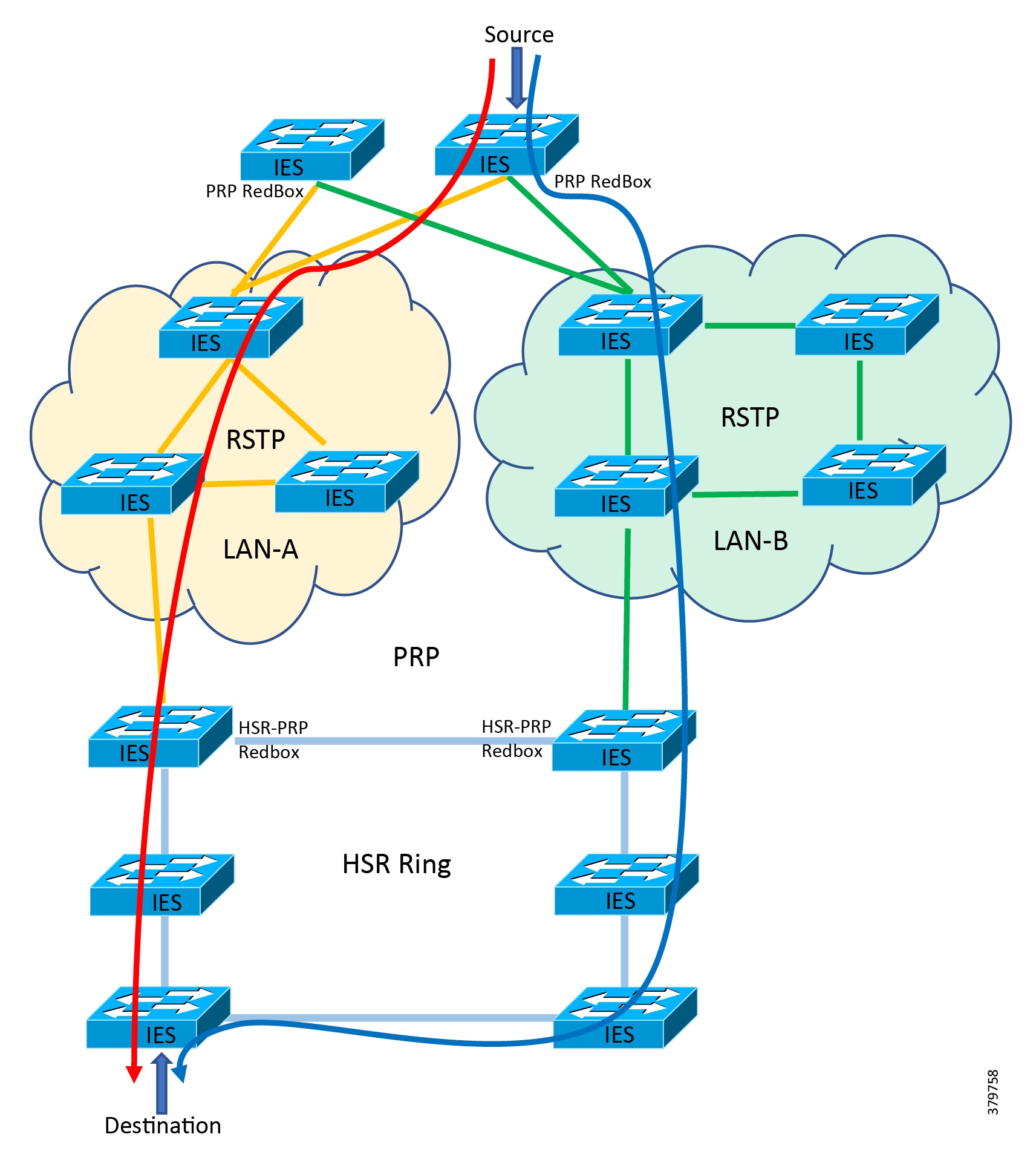
Follow these steps to configure HSR-PRP mode on the switch. Enabling HSR-PRP mode creates an HSR ring and a PRP channel.
Before You Begin
■![]() Enabling HSR-PRP mode will disable all ports other than two HSR ports and one PRP port and all port settings for these disabled ports will return to default values. A warning message is displayed to notify you that interface configurations will be removed. Before enabling or disabling HSR-PRP mode, check for cables connected to the switch and verify the ports' status.
Enabling HSR-PRP mode will disable all ports other than two HSR ports and one PRP port and all port settings for these disabled ports will return to default values. A warning message is displayed to notify you that interface configurations will be removed. Before enabling or disabling HSR-PRP mode, check for cables connected to the switch and verify the ports' status.
■![]() HSR-PRP RedBox mode uses ports Gi1/3 and Gi1/4 as HSR ring 2 interfaces and Gi1/1 (for RedBox A) or Gi1/2 (for RedBox B) as PRP channel 1 interfaces. These port assignments are fixed and cannot be changed. Therefore, HSR-PRP Dual RedBox mode is supported only on HSR ring 2.
HSR-PRP RedBox mode uses ports Gi1/3 and Gi1/4 as HSR ring 2 interfaces and Gi1/1 (for RedBox A) or Gi1/2 (for RedBox B) as PRP channel 1 interfaces. These port assignments are fixed and cannot be changed. Therefore, HSR-PRP Dual RedBox mode is supported only on HSR ring 2.
■![]() PRP uplink interfaces can be configured as access, trunk, or routed interfaces.
PRP uplink interfaces can be configured as access, trunk, or routed interfaces.
■![]() PRP Dual Attached Nodes and RedBoxes add a 6-byte PRP trailer to the packet. To ensure that all packets can flow through the PRP network, increase the maximum transmission unit (MTU) size for switches within the PRP LAN-A and LAN-B network to 1506 as follows:
PRP Dual Attached Nodes and RedBoxes add a 6-byte PRP trailer to the packet. To ensure that all packets can flow through the PRP network, increase the maximum transmission unit (MTU) size for switches within the PRP LAN-A and LAN-B network to 1506 as follows:
■![]() When an intelligent electronic device (IED) sends VLAN 0 tagged packets, it is recommended to configure the IED facing interface and the uplink interfaces as trunk port allowing VLAN 1 along with other required VLANs:
When an intelligent electronic device (IED) sends VLAN 0 tagged packets, it is recommended to configure the IED facing interface and the uplink interfaces as trunk port allowing VLAN 1 along with other required VLANs:
Recommended Best Practices
■![]() Disable PTP on interfaces where PTP is not necessary.
Disable PTP on interfaces where PTP is not necessary.
■![]() Enable storm control for broadcast, multicast traffic on access facing interfaces:
Enable storm control for broadcast, multicast traffic on access facing interfaces:
■![]() Configure different VLANs for different IEDs so as to avoid flooding of multicast, broadcast messages to other devices.
Configure different VLANs for different IEDs so as to avoid flooding of multicast, broadcast messages to other devices.
Configuring HSR-PRP RedBox
1. ![]() Activate HSR feature mode:
Activate HSR feature mode:
Note: Reload the switch for the change to take effect. Confirm the reload when prompted and wait for the switch to reload and boot.
2. ![]() Verify that the HSR feature is activated:
Verify that the HSR feature is activated:
3. ![]() Enter global configuration mode:
Enter global configuration mode:
4. ![]() Enable HSR-PRP mode and select LAN A or LAN B and the PRP Net ID:
Enable HSR-PRP mode and select LAN A or LAN B and the PRP Net ID:
Note: PRP LAN: prp-lan-a-RedBox Interlink is connected to lan-A. prp-lan-b-RedBox Interlink is connected to lan-B.
5. ![]() Enter yes to confirm enabling HSR-PRP mode. To disable HSR-PRP RedBox mode, use the command:
Enter yes to confirm enabling HSR-PRP mode. To disable HSR-PRP RedBox mode, use the command:
6. ![]() Enter interface configuration mode and disable PTP on the ports to be assigned to the HSR ring:
Enter interface configuration mode and disable PTP on the ports to be assigned to the HSR ring:
Note: The PTP feature over HSR ring is currently not supported.
7. ![]() Shut down the ports before configuring the HSR ring:
Shut down the ports before configuring the HSR ring:
8. ![]() Create the HSR ring interface:
Create the HSR ring interface:
9. ![]() Assign HSR ring to the physical interfaces:
Assign HSR ring to the physical interfaces:
10. ![]() Create the PRP LAN interface. Repeat the step on the second HSR-PRP RedBox.
Create the PRP LAN interface. Repeat the step on the second HSR-PRP RedBox.
11. ![]() Assign PRP channel to the physical interface. Follow the guidelines for identifying the switch role and the corresponding interface.
Assign PRP channel to the physical interface. Follow the guidelines for identifying the switch role and the corresponding interface.
| | | | |
| | | | |
| | |
12. ![]() Refer to Configuring HSR to configure HSR ring on other switches that are part of the HSR ring.
Refer to Configuring HSR to configure HSR ring on other switches that are part of the HSR ring.
13. ![]() Refer to PRP RedBox Configuration to configure PRP on required switches that are part of the PRP network.
Refer to PRP RedBox Configuration to configure PRP on required switches that are part of the PRP network.
Troubleshooting HSR-PRP RedBox
Use the following commands to verify and troubleshoot HSR-PRP Redbox:
Configure HSR-PRP RedBox Using Device Manager
This section assumes that the Cisco IE switch has been installed and configured with an IP address for remote access. For more details on setting up a Cisco IE switch, refer to the corresponding installation guides.
1. ![]() Log in to the switch using Device Manager credentials.
Log in to the switch using Device Manager credentials.
Figure 110 Device Manager Login Screen
2. ![]() After a successful login, the Dashboard for the switch loads.
After a successful login, the Dashboard for the switch loads.
Figure 111 Cisco IE 4000 Device Manager Dashboard
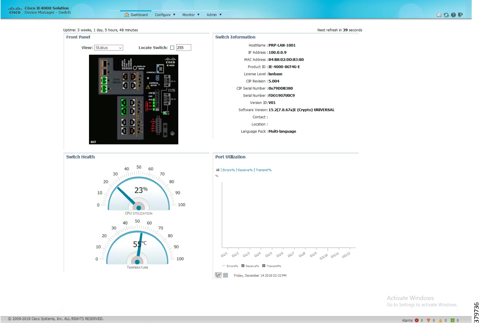
3. ![]() Enable the HSR feature on the Cisco IE switch using the options highlighted in Figure 112. Select the Admin tab, select the Feature Mode option, and then select HSR as the required feature mode.
Enable the HSR feature on the Cisco IE switch using the options highlighted in Figure 112. Select the Admin tab, select the Feature Mode option, and then select HSR as the required feature mode.
Figure 112 Enable HSR Feature
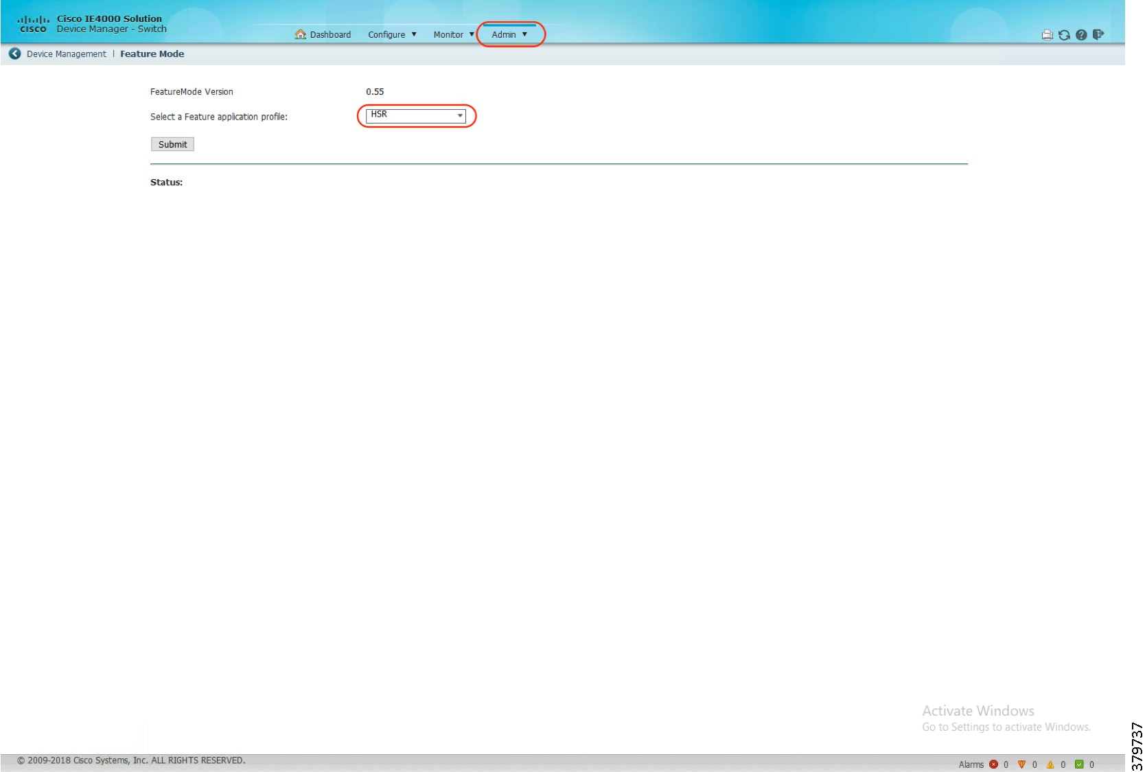
4. ![]() Configure HSR-PRP Redbox by selecting the highlighted steps in Figure 113.
Configure HSR-PRP Redbox by selecting the highlighted steps in Figure 113.
Figure 113 Configure HSR Feature
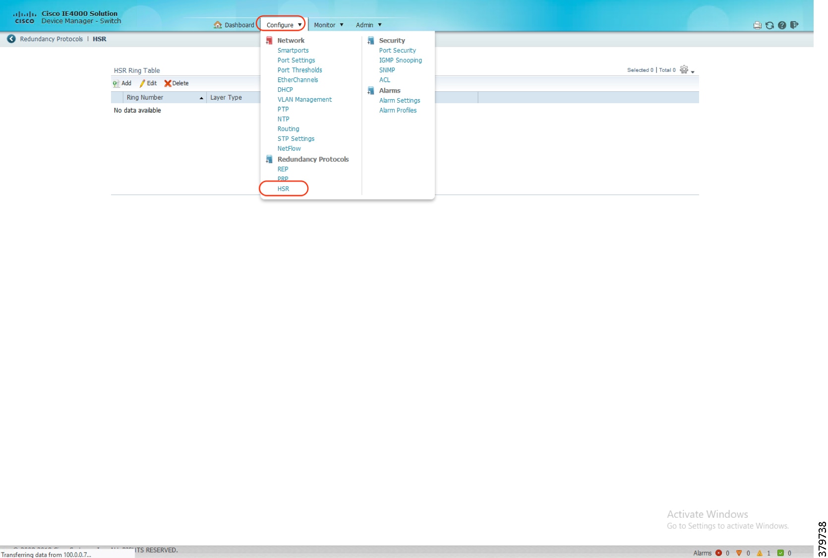
5. ![]() Configure HSR-PRP Redbox parameters on the Cisco IE switch using the options highlighted in Figure 114.
Configure HSR-PRP Redbox parameters on the Cisco IE switch using the options highlighted in Figure 114.
Figure 114 Configure HSR-PRP Parameters
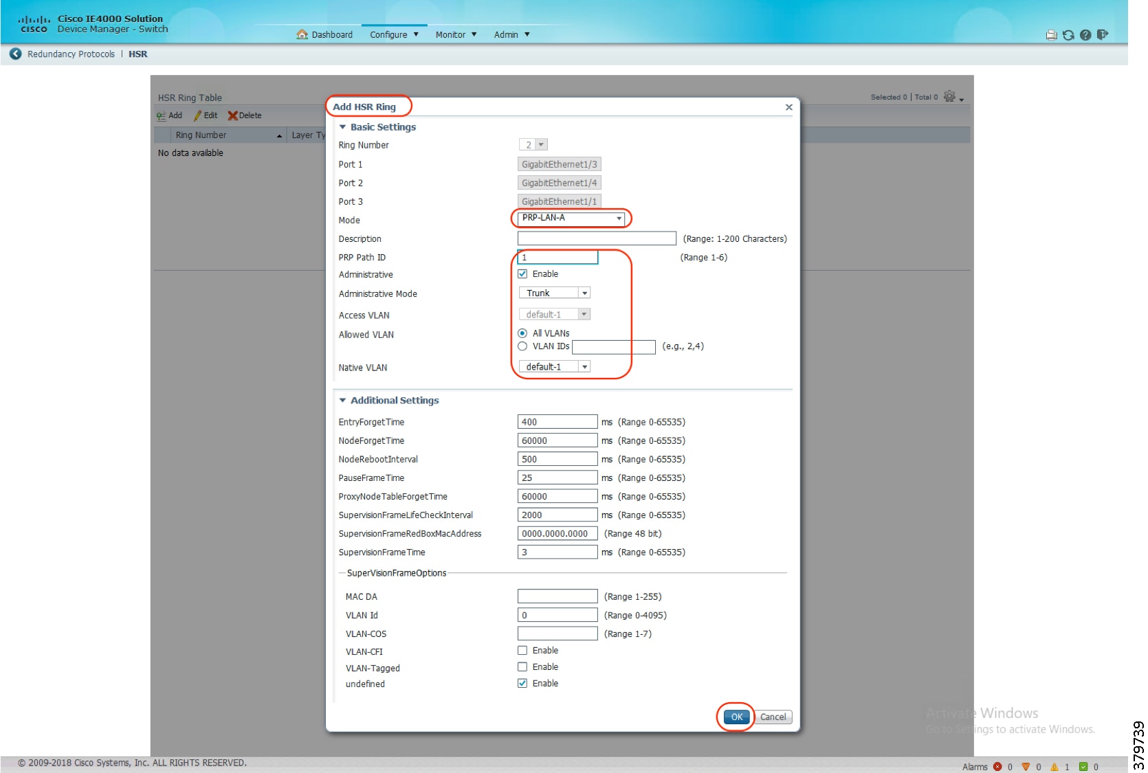
PRP RedBox Configuration
| | |
| | |
| | |
| | |
To create and enable a PRP channel and group on a supported Cisco IE switch, follow these steps:
1. ![]() Enter global configuration mode.
Enter global configuration mode.
2. ![]() Create PRP LAN interface:
Create PRP LAN interface:
3. ![]() Attach PRP channel to the physical interface. Follow the guidelines for identifying the switch role and the corresponding interface.
Attach PRP channel to the physical interface. Follow the guidelines for identifying the switch role and the corresponding interface.
| SKU | Interface Mapping |
|---|---|
| IE4000 | PRP channel group 1 always uses Gi1/1 for LAN_A and Gi1/2 for LAN_B PRP channel group 2 always uses Gi1/3 for LAN_A and Gi1/4 for LAN_B |
| IE4010 | PRP channel group 1 always uses Gi1/25 for LAN_A and Gi1/26 for LAN_B PRP channel group 2 always uses Gi1/27 for LAN_A and Gi1/28 for LAN_B |
| IE5000 | PRP channel group 1 always uses Gi1/17 for LAN_A and Gi1/18 for LAN_BP RP channel group 2 always uses Gi1/19 for LAN_A and Gi1/20 for LAN_B |
Configure and Monitor PRP RedBox Using Device Manager
This section assumes that the Cisco IE switch has been installed and configured with an IP address for remote access. For more details on setting up a Cisco IE switch, refer to the corresponding installation guides.
1. ![]() Log in to the switch using Device Manager credentials.
Log in to the switch using Device Manager credentials.
Figure 115 Device Manager Login Screen
2. ![]() After a successful login, the Dashboard for the switch loads.
After a successful login, the Dashboard for the switch loads.
Figure 116 Device Manager Dashboard
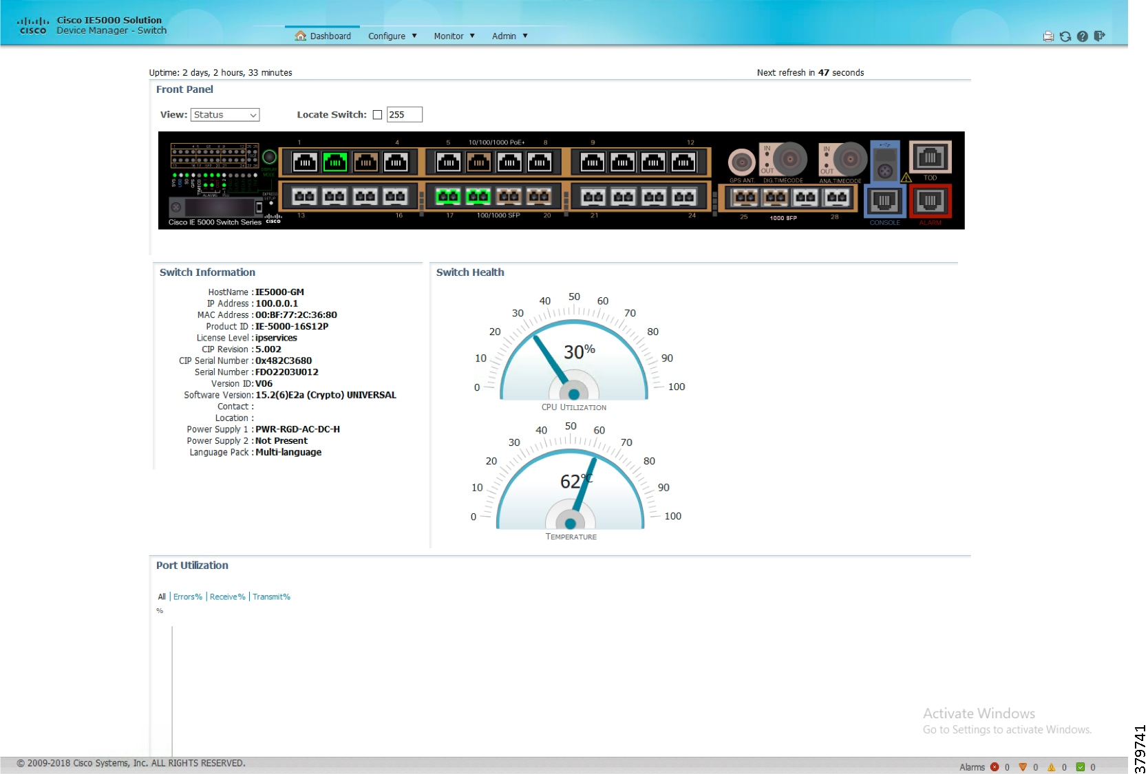
3. ![]() Configure PRP by selecting the PRP option under the Configure tab as highlighted in Figure 117.
Configure PRP by selecting the PRP option under the Configure tab as highlighted in Figure 117.
Figure 117 Configure PRP Using Device Manager
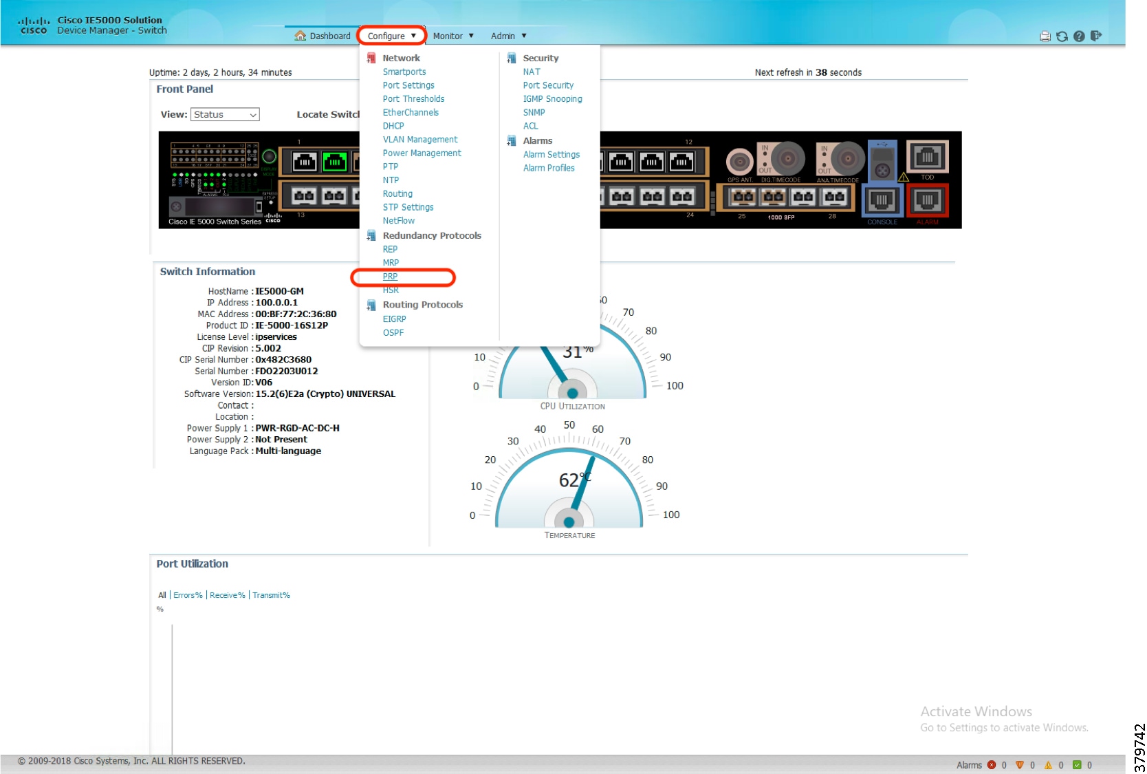
4. ![]() Configure PRP Channel properties like channel number, switchport mode, allowed VLANs, native VLANs, and so on as highlighted in Figure 118.
Configure PRP Channel properties like channel number, switchport mode, allowed VLANs, native VLANs, and so on as highlighted in Figure 118.
Figure 118 Configure PRP Channel Properties
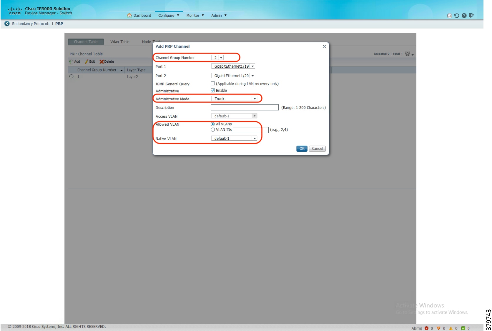
5. ![]() The status of the PRP Channel would be reflected as soon as the configuration of the PRP channel is completed as highlighted in Figure 119.
The status of the PRP Channel would be reflected as soon as the configuration of the PRP channel is completed as highlighted in Figure 119.
Figure 119 PRP Channel Status
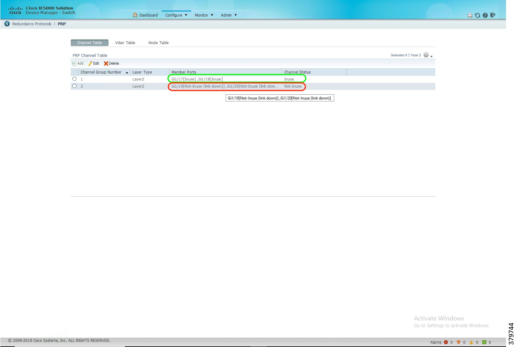
6. ![]() Select the PRP option listed under the Monitor tab to check details of VDAN and Node table details.
Select the PRP option listed under the Monitor tab to check details of VDAN and Node table details.
Figure 120 Monitor PRP
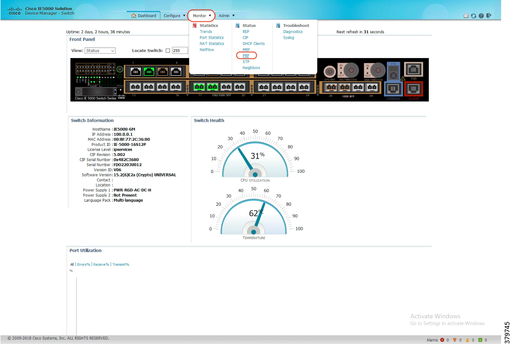
PTP over PRP
PTP is defined in IEEE 1588 as Precision Clock Synchronization for Networked Measurements and Control Systems and was developed to synchronize the clocks in packet-based networks that include distributed device clocks of varying precision and stability. PTP is designed specifically for industrial networked measurement and control systems and is optimal for use in distributed systems because it requires minimal bandwidth and little processing overhead.
Previously, PTP traffic was allowed only on LAN-A of PRP. However, if LAN-A went down, PTP synchronization was lost. To enable PTP to leverage the benefit of redundancy offered by PRP infrastructure, PTP packets over PRP networks are handled differently than other types of traffic. The current implementation of PTP over PRP does not append a Recovery Control Task (RCT) to PTP packets and bypasses the PRP duplicate/discard logic for PTP packets.
Follow these steps to configure PTP over PRP network.
Note: The PTP feature over HSR ring is currently not supported.
Figure 121 PTP over PRP
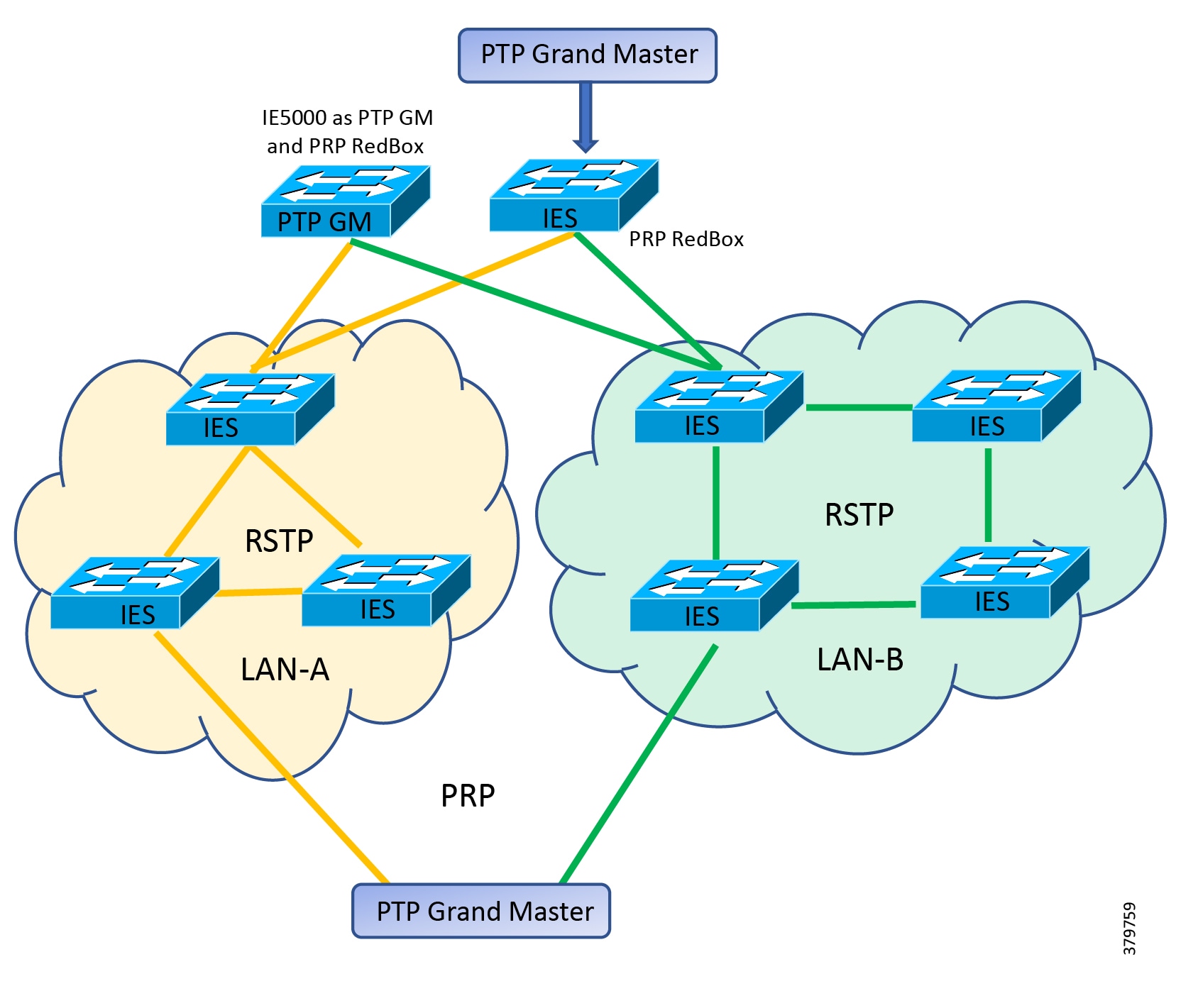
Before You Begin
The grandmaster (GM) can be located in a PTP over PRP topology as one of the following:
■![]() A Redbox connected to both LAN A and LAN B (PTP grandmaster as RedBox).
A Redbox connected to both LAN A and LAN B (PTP grandmaster as RedBox).
■![]() A VDAN connected to a PRP RedBox (PTP grandmaster connected to a PRP RedBox).
A VDAN connected to a PRP RedBox (PTP grandmaster connected to a PRP RedBox).
■![]() A DAN (PTP grandmaster clock directly attached to both LANs of PRP).
A DAN (PTP grandmaster clock directly attached to both LANs of PRP).
The PTP grandmaster cannot be attached either to LAN-A or LAN-B because only the devices in LAN-A or LAN-B will be synchronized to the GM.
The switch sends untagged PTP packets on the native VLAN when the switch port connected to the grandmaster clock is configured as follows:
■![]() Switch is in Default Profile mode.
Switch is in Default Profile mode.
■![]() Switch is in trunk mode.
Switch is in trunk mode.
■![]() VLAN X is configured as the native VLAN.
VLAN X is configured as the native VLAN.
When the grandmaster clock requires tagged packets, make one of the following configuration changes:
■![]() Force the switch to send tagged frames by entering the global vlan dot1q tag native command:
Force the switch to send tagged frames by entering the global vlan dot1q tag native command:
■![]() Configure the grandmaster clock to send and receive untagged packets. If you make this configuration change on the grandmaster clock, you can configure the switch port as an access port.
Configure the grandmaster clock to send and receive untagged packets. If you make this configuration change on the grandmaster clock, you can configure the switch port as an access port.
■![]() Force the switch to tag PTP packets by entering the interface level command ptp vlan <>. With this configuration change, the switch would tag all PTP packets traversing through the interface with the corresponding VLAN.
Force the switch to tag PTP packets by entering the interface level command ptp vlan <>. With this configuration change, the switch would tag all PTP packets traversing through the interface with the corresponding VLAN.
When the network requires Class of Service (COS) values for PTP packets to be set, make one of the following configuration changes:
■![]() The switch by default sets the COS value to 4 to all tagged PTP packets according to the IEEE C37.238 standard in PTP Power profile mode.
The switch by default sets the COS value to 4 to all tagged PTP packets according to the IEEE C37.238 standard in PTP Power profile mode.
■![]() Force the switch to set COS value for PTP packets by entering global ptp packet command:
Force the switch to set COS value for PTP packets by entering global ptp packet command:
Recommended Practices
■![]() Disable PTP on interfaces where PTP is not necessary.
Disable PTP on interfaces where PTP is not necessary.
■![]() Configure peer-to-peer transparent mode for PTP transparent clocks to reduce jitter and delay accumulation:
Configure peer-to-peer transparent mode for PTP transparent clocks to reduce jitter and delay accumulation:
■![]() Configure the switch to process non-PTP compliant PTP Grandmaster sending announce messages without Organization_extension and Alternate_timescale TLVs using the following command:
Configure the switch to process non-PTP compliant PTP Grandmaster sending announce messages without Organization_extension and Alternate_timescale TLVs using the following command:
■![]() In interoperability scenarios, its best to use the default PTP domain value which as per C37.238:2011 standard is 0 (zero).The default PTP domain value on Cisco IE switches is set to 0 (zero). It can also be configured using the following command:
In interoperability scenarios, its best to use the default PTP domain value which as per C37.238:2011 standard is 0 (zero).The default PTP domain value on Cisco IE switches is set to 0 (zero). It can also be configured using the following command:
Configuring PRP RedBox
PRP is designed to provide zero recovery time after failures in Ethernet networks. PRP allows a data communication network to prevent data transmission failures by providing network nodes two alternate paths for the traffic to reach its destination. Two LANs) provide alternate paths for the traffic over independent LAN segments. A switch configured for PRP mode has one gigabit Ethernet port connecting each of the two LANs. The switch sends two packets simultaneously to each LAN through the two different ports to the destination node. The destination node discards duplicate packets.
To create and enable a PRP channel and group on a supported Cisco IE switch, follow these steps:
1. ![]() Enter global configuration mode:
Enter global configuration mode:
2. ![]() Create PRP LAN interface:
Create PRP LAN interface:
3. ![]() Attach PRP channel to the physical interface. Follow the guidelines for identifying the switch role and the corresponding interface.
Attach PRP channel to the physical interface. Follow the guidelines for identifying the switch role and the corresponding interface.
| SKU | Interface Mapping |
|---|---|
| IE4000 | PRP channel group 1 always uses Gi1/1 for LAN_A and Gi1/2 for LAN_B PRP channel group 2 always uses Gi1/3 for LAN_A and Gi1/4 for LAN_B |
| IE4010 | PRP channel group 1 always uses Gi1/25 for LAN_A and Gi1/26 for LAN_B PRP channel group 2 always uses Gi1/27 for LAN_A and Gi1/28 for LAN_B |
| IE5000 | PRP channel group 1 always uses Gi1/17 for LAN_A and Gi1/18 for LAN_B PRP channel group 2 always uses Gi1/19 for LAN_A and Gi1/20 for LAN_B |
Configuring PTP over PRP
1. ![]() Enter global configuration mode:
Enter global configuration mode:
2. ![]() Set the Power Profile:
Set the Power Profile:
3. ![]() Specify the synchronization clock mode:
Specify the synchronization clock mode:
–![]() mode boundary pdelay-req—Configures the switch for boundary clock mode using the delay-request mechanism. In this mode, the switch participates in the selection of the most accurate primary clock. Use this mode when overload or heavy load conditions produce significant delay jitter.
mode boundary pdelay-req—Configures the switch for boundary clock mode using the delay-request mechanism. In this mode, the switch participates in the selection of the most accurate primary clock. Use this mode when overload or heavy load conditions produce significant delay jitter.
–![]() mode p2ptransparent—Configures the switch for peer-to-peer transparent clock mode and synchronizes all switch ports with the primary clock. The link delay time between the participating PTP ports and the message transit time is added to the resident time. Use this mode to reduce jitter and error accumulation. This is the default in Power Profile mode.
mode p2ptransparent—Configures the switch for peer-to-peer transparent clock mode and synchronizes all switch ports with the primary clock. The link delay time between the participating PTP ports and the message transit time is added to the resident time. Use this mode to reduce jitter and error accumulation. This is the default in Power Profile mode.
–![]() mode forward—Configures the switch to pass incoming PTP packets as normal multicast traffic.
mode forward—Configures the switch to pass incoming PTP packets as normal multicast traffic.
4. ![]() Specify TLV settings:
Specify TLV settings:
5. ![]() Specify synchronization algorithm if the switch is configured as PTP Boundary Clock:
Specify synchronization algorithm if the switch is configured as PTP Boundary Clock:
–![]() feedforward -Very fast and accurate. No PDV filtering.
feedforward -Very fast and accurate. No PDV filtering.
–![]() filter linear -Provides a simple linear filter (default).
filter linear -Provides a simple linear filter (default).
Troubleshooting PTP over PRP
Use the following commands to check PTP clock type, GrandMaster properties, and clock source.
Boundary Clock Example:
Peer-to-Peer Transparent Clock Example:
On a Cisco IE 5000 switch acting as PRP Redbox and also as PTP grandmaster, the PTP state on PRP member ports can be checked using the following command. Both the PRP member ports should have a port state of MASTER.
On a Cisco IE 5000 switch acting as PRP Redbox and PTP Boundary clock, the PTP state on PRP member ports can be checked using the following command. The state of the active port should be SLAVE and the other as PASSIVE_SLAVE. If the active port fails, the other port changes the state to SLAVE.
Cisco IE 5000 as PTP Grandmaster
Cisco IE switches are capable of accurate time distribution using PTP or IRIG-B, but previously relied on an external source to provide accurate time. The Cisco IE 5000 switch has a built-in Global Navigation Satellite System (GNSS) receiver that enables the switch to determine its own location and get accurate time from a satellite constellation. The switch can become the PTP grandmaster clock for time distribution in the network.
Before You Begin
GNSS is supported only on Cisco IE 5000 switches with SKUs that have Version ID (VID) v05 or higher and GNSS firmware version 1.04 or higher. Verify using show version output:
The GNSS feature is available for all feature sets ( lanbase, ipservices) and does not require a separate license.
GNSS can be used as time source for PTP default and Power profiles only.
GNSS can be used as time source for PTP in GMC-BC mode only.
Configuring PTP Grandmaster
1. ![]() Enter global configuration mode:
Enter global configuration mode:
2. ![]() Enable GNSS.
Enable GNSS.
3. ![]() Configure the switch for grandmaster-boundary clock mode:
Configure the switch for grandmaster-boundary clock mode:
Troubleshooting PTP Grandmaster
Quality of Service
This section describes how Quality of Service (QoS) works in industrial automation environments and specifies the major QoS design considerations when deploying Cisco industrial switches into industrial automation networks.
QoS is an enabling technology inside the industrial automation network. Cisco IE switches employ a built-in Express Setup and Smart-ports method to facilitate simple deployment without having to take additional steps. However, studying and understanding the QoS solution and its performance implication is a very important task for the industrial automation solution development team.
QoS refers to network control mechanisms that can provide various priorities to different industrial automation devices or traffic flows or to guarantee a certain level of performance of a traffic flow in accordance with requests from the application program. By providing dedicated bandwidth, controlled jitter and latency (required by some real-time and interactive traffic), and improved loss characteristics, QoS can ensure better service for selected network traffic.
Traffic Flows
Traffic flows in an industrial automation network have very different traffic patterns compared to client server-based applications in the IT network. For example:
■![]() Cyclical I/O data is communicated on very short intervals (milliseconds) from devices to controllers and human-machine interfaces (HMIs) or workstations, all on the same network segment and mainly remaining in the local Cell/Area Zone.
Cyclical I/O data is communicated on very short intervals (milliseconds) from devices to controllers and human-machine interfaces (HMIs) or workstations, all on the same network segment and mainly remaining in the local Cell/Area Zone.
■![]() Industrial devices utilize unique Differentiated Services Code Point (DSCP) marking to identify itself with IT management traffic flows. For example, PTP event marked with DSCP 59, PTP management marked with DSCP 47, ODVA, Inc. Common Industrial Protocol (CIP) class urgent marked with DSCP 55, and so on.
Industrial devices utilize unique Differentiated Services Code Point (DSCP) marking to identify itself with IT management traffic flows. For example, PTP event marked with DSCP 59, PTP management marked with DSCP 47, ODVA, Inc. Common Industrial Protocol (CIP) class urgent marked with DSCP 55, and so on.
■![]() Different types of industrial automation network traffic (Motion, I/O, and HMI) have different requirements for latency, packet loss, and jitter. The service policy should differentiate service for these types of traffic flows.
Different types of industrial automation network traffic (Motion, I/O, and HMI) have different requirements for latency, packet loss, and jitter. The service policy should differentiate service for these types of traffic flows.
■![]() OT traffic typically is pulse-based with very small packet size.
OT traffic typically is pulse-based with very small packet size.
■![]() IT and OT traffic often coexist together inside the industrial automation network. OT traffic take precedence over other IT management network traffic flows.
IT and OT traffic often coexist together inside the industrial automation network. OT traffic take precedence over other IT management network traffic flows.
Figure 122, Table 58, and Table 59 illustrate a typical industrial automation network traffic flow, traffic types, and differentiated service marking.
Figure 122 Industrial Automation Plant Manufacture Zone Traffic Flow
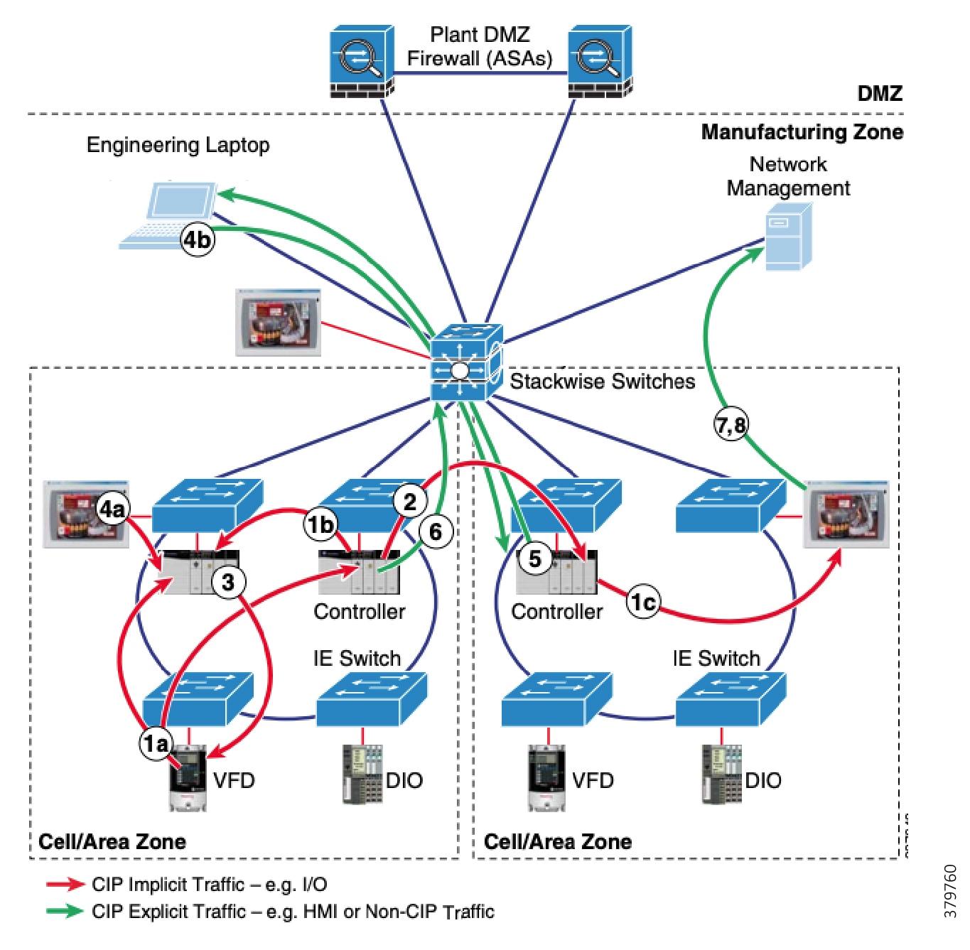
| | | | | | | |
| | | | | | | |
| | | | | | | |
| | | | | | | |
| | | | | | | |
| | | | | | | |
| | | | | | | |
| | | | | | | |
| | | | | | | |
| | | | | |
| | | | | |
| | | | | |
| | | | | |
| | | | | |
| | | | | |
| | | | | |
| | | | | |
Network Devices and QoS Models
Industrial automation plants adopt a common and well-understood Purdue model (reference ISBN 1-55617-265-6) for Control Hierarchy so as to segment network devices and functions into different functioning zones for easy management. Every segment deploys many different kinds of switches and routers with different network architecture and feature sets. In order to streamline all traffic flow and different network services and reduce packet loss, jitter, and latency, a well-designed QoS model is very important to guarantee network performance and operation.
Figure 123 shows a typical QoS model designed for Cell/Area Zone area inside an industrial automation plant, where multiple Cisco IE switches (Cisco IE 2000, Cisco IE 3x00, Cisco IE 4000, Cisco Catalyst 3850, and Cisco Catalyst 9300, and so on) inter-connected form an ingress and egress pipeline to classify and police network traffic flows.
Figure 123 Industrial Automation Plant Manufacture Zone QoS Model
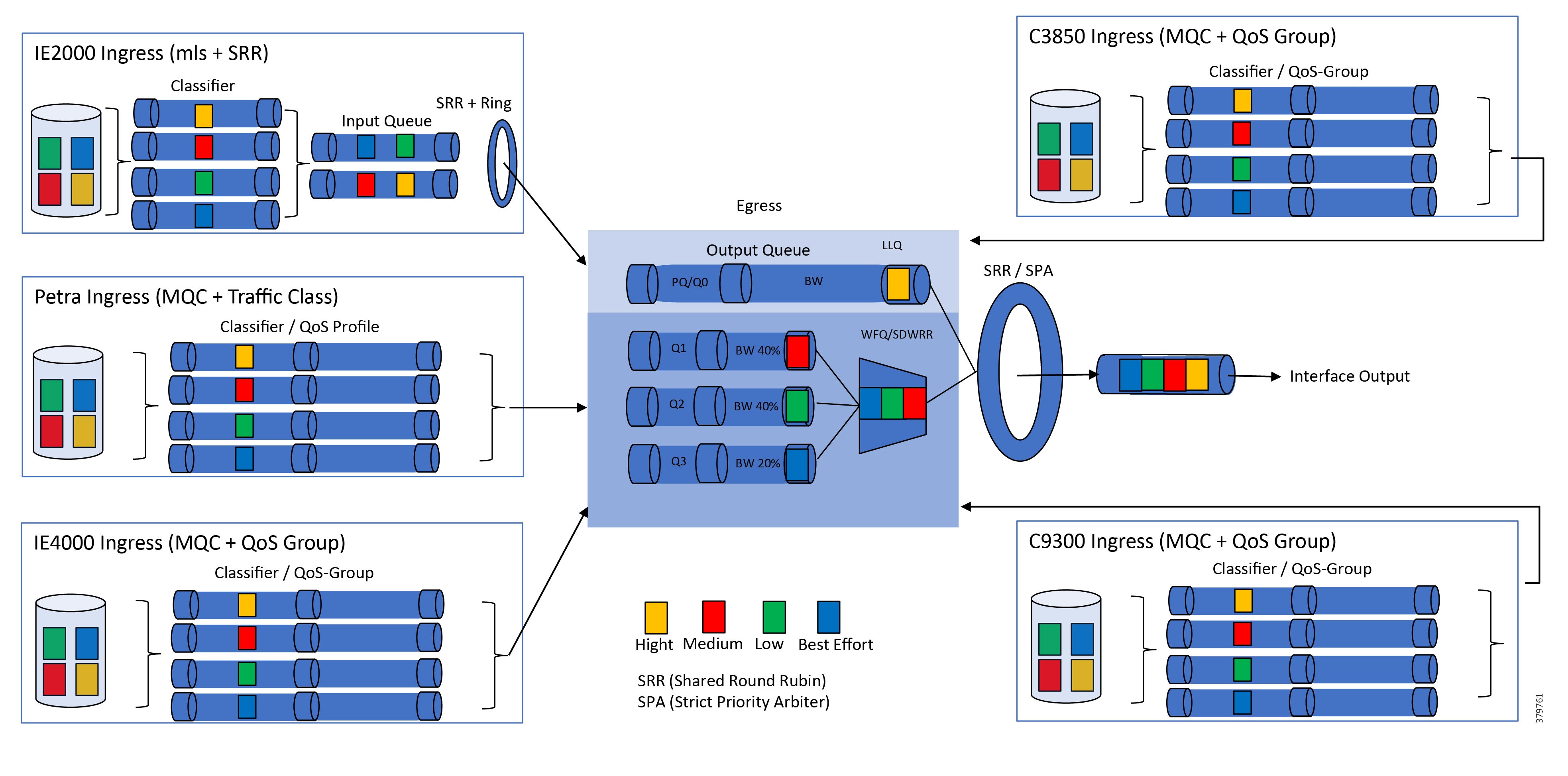
Cisco IE 2000 Industrial Ethernet Switch
The Cisco IE 2000 mainly assumes an access switch role to bridge industrial Program Logic Controller (PLC). The Cisco IE 2000 utilizes Multilayer Switching QoS (MLS) globally and establishes the trust boundary for the overall network. This is achieved by correctly classifying network traffic flows based on their protocol, ports, and QoS marking. The ingress side has two queues consisting of priority Queue and Shaped Round Robin (SRR) shared queue. Through a transmit ring, network traffic feeds into the egress side policed with one priority queue and three shared SRR queues for weighted bandwidth allocation and traffic enters into a transmit ring to exit the egress interface.
Cisco IE 3x00 Series Industrial Ethernet Switch
The Cisco IE 3x00 switch is the next generation switch replacing the Cisco IE 3000. It utilizes a Modular QoS Class (MQC) model along with ASIC pre-programmed Traffic Profile to classify network traffic and establish trust boundary. A simplified hardware architecture enables a QoS data plane entirely on an ASIC. Ingress side packet classification, marking, and policing are performed using either ASIC codepoint-based tables or TCAM rules. Packet enqueue and scheduling profile are decided based on the QoS Profile. Egress side packet enqueuing, scheduling, and shaping are performed. Different QoS packets will be mapped into packet 128 QoS profiles. Shaped Deficit Weighted Round Robin (SDWRR) provide dynamic enqueue and dequeue handling as compared with Weighted Round Robin (WRR). A Strict Priority Arbiter (SPA) can expedite mission critical packet handling in egress ports.
Cisco IE 4000 Industrial Ethernet Switch
The Cisco IE 4000 with more port density, compute power, and multiple industrial protocol support assumes either access layer switch or a distribution switch. It utilizes MQC and QoS Group to classify traffic and police them into the correct queue. A class-based Weighted Fair Queue (WFQ) with Priority Queue (PQ) is chosen to police traffic on the egress side. The Cisco IE 4000 does not have a SRR transmit ring.
Cisco Catalyst 3850 Network Switch
Cisco Catalyst 3850 StackWise switches are the cell/zone area gateway devices to interconnect Layer 2 device ring/chain with Layer 3 network infrastructures. The Cisco Catalyst 3850 switch utilizes MQC and QoS-Group for ingress traffic classification and policing. Network traffic enters into a StackWise ring and feeds into egress 1 Priority Queue and 3 Weighted Fair Queue (WFQ). An egress port SRR shaper provides weighted bandwidth allocation between different traffic classes.
Cisco Catalyst 9300 Network Switch
Cisco Catalyst 9300 StackWise switches provide a cloud ready software defined access (SD-Access). It utilizes policy-based automation from edge to cloud, which can incorporate mobility, IoT, cloud, and security in one portfolio. The Csco Catalyst 9300 utilizes a similar QoS model as the Cisco Catalyst 3850 StackWise switch. UADP 2.0 ASIC incorporates template-based configurable QoS entries to ensure Superior QoS, including granular wireless bandwidth management, fair sharing, 802.1p Class of Service (CoS), Differentiated Services Code Point (DSCP) field classification, Shaped Round Robin (SRR) scheduling, Committed Information Rate (CIR), and eight egress queues per port.
Traffic Classification
The first element in a QoS policy is to classify/identify the traffic that is to be treated differently. Classification and marking tools set this trust boundary by examining any of the following:
■![]() Layer 2 parameters—802.1Q class-of-service (CoS) bits
Layer 2 parameters—802.1Q class-of-service (CoS) bits
■![]() Layer 3 parameters—IP Precedence (IPP), Differentiated Services Code Points (DSCP), IP Explicit Congestion Notification (ECN), and source/destination IP address
Layer 3 parameters—IP Precedence (IPP), Differentiated Services Code Points (DSCP), IP Explicit Congestion Notification (ECN), and source/destination IP address
■![]() Layer 4 parameters— Layer 4 protocol (TCP or UDP) and source and destination ports
Layer 4 parameters— Layer 4 protocol (TCP or UDP) and source and destination ports
■![]() Layer 7 parameters—Application signatures
Layer 7 parameters—Application signatures
The QoS model implemented in Cisco IE switches focuses on the Differentiated Services or DiffServ model. One of the key goals of DiffServ is to classify and mark the traffic as close to the source as possible. This allows for an end-to-end model where intermediary routers and switches simply forward the frame based on the predetermined marking. Do not trust markings that can be set by users on their PCs or other similar devices, because users can easily abuse provisioned QoS policies if permitted to mark their own traffic.
Following classification, marking tools can set an attribute of a frame or packet to a specific value. Such marking (or remarking) establishes a trust boundary that scheduling tools later depend on.
Figure 124 Industrial Automation Plant Manufacture QoS Trust Boundary

The following steps describe ingress QoS implementation:
1. ![]() Establish ACLs for each industrial automation network traffic type. This will allow the industrial Ethernet switch to filter the network traffic based upon key characteristics like transport protocol (UDP or TCP), port type (CIP Explicit messages or Implicit I/O), or existing DSCP value.
Establish ACLs for each industrial automation network traffic type. This will allow the industrial Ethernet switch to filter the network traffic based upon key characteristics like transport protocol (UDP or TCP), port type (CIP Explicit messages or Implicit I/O), or existing DSCP value.
2. ![]() Set up class-maps to match the ACL-filtered traffic with a classification.
Set up class-maps to match the ACL-filtered traffic with a classification.
3. ![]() Set up a policy map that assigns classification to class-maps.
Set up a policy map that assigns classification to class-maps.
4. ![]() Assign the service policy to each port that transports industrial automation network traffic.
Assign the service policy to each port that transports industrial automation network traffic.
Policing, Queuing, and Scheduling
Network device egress port can use policing, queuing, and scheduling tools to manage traffic flow priority by putting mission critical traffic into priority queue and allocating the correct amount of bandwidth across all traffic classes. The following sections describe each of the building blocks of an egress QoS model.
Policing
Policing is a mechanism to limit the bandwidth of any traffic class and can be used on any port.
Policing can result in three actions:
■![]() No action if the bandwidth is not exceeded.
No action if the bandwidth is not exceeded.
■![]() If the bandwidth is exceeded, the packet may be dropped.
If the bandwidth is exceeded, the packet may be dropped.
■![]() If the bandwidth is exceeded, the packet may be "marked down" where the classification is modified to presumably lower its priority.
If the bandwidth is exceeded, the packet may be "marked down" where the classification is modified to presumably lower its priority.
Queuing
Queuing establishes buffers to handle packets as they arrive at the switch (ingress) and leave the switch (egress). Each port on the switch has ingress and egress queues. Both the ingress and egress queues use an enhanced version of the tail-drop congestion-avoidance mechanism called weighted tail drop (WTD). WTD is implemented on queues to manage the queue lengths and to provide drop precedence for different traffic classifications. Each queue has three thresholds to proactively drop packets before queues fill up. Traffic classes assigned to thresholds 1 or 2 will be dropped if the queue buffer has reached the assigned threshold. Traffic classes assigned to a threshold of 3 for a specific queue will only be dropped if that queue has filled its buffer space.
| | | | | | | | | | ||||
| | | | | | | | | | ||||
| | | | | | | | | | | | | |
| | | | | | | | | | ||||
| | | | ||||||||||
| | | | | | | |||||||
| | | | | | ||||||||
| | | | | | | | | |||||
| | | | | | |
| | | | | | |
| | | | | | |
| | | | | | | |
| | | | | | | |
| | | | | | | |
| | | | PTP Management, CIP Implicit I/O, Network Control, and Voice data | | | |
| | | | | | | |
Scheduling
Both the ingress and egress queues are serviced by either Shared Round-Robin (SRR) scheduling or Strict Priority Arbiter (SPA, Cisco IE 3x00 Series Switch), which controls the rate at which packets are sent.
The following are the general configuration steps for egress side QoS:
1. ![]() Enable priority queue out (queue 1) on all switch ports carrying IACS network traffic (access and trunk ports). This ensures the highest priority traffic assigned to the queue will be serviced quickly. This queue will no longer be serviced as a shared round-robin and any SRR settings for that port will not be in effect.
Enable priority queue out (queue 1) on all switch ports carrying IACS network traffic (access and trunk ports). This ensures the highest priority traffic assigned to the queue will be serviced quickly. This queue will no longer be serviced as a shared round-robin and any SRR settings for that port will not be in effect.
2. ![]() Assign specific queues for IACS network traffic and other priority traffic, if it exists (for example, Voice and Network Routing traffic). These queues are then assigned buffers and scheduling weights to minimize packet loss and optimize scheduling. Maintain 1 ingress and egress queue for other traffic. For ingress, queue 1 is for other traffic. For egress, queue 2 (of 4) is for best effort traffic.
Assign specific queues for IACS network traffic and other priority traffic, if it exists (for example, Voice and Network Routing traffic). These queues are then assigned buffers and scheduling weights to minimize packet loss and optimize scheduling. Maintain 1 ingress and egress queue for other traffic. For ingress, queue 1 is for other traffic. For egress, queue 2 (of 4) is for best effort traffic.
3. ![]() Map IACS network traffic to specific queues via COS and DSCP maps for each queue and threshold. IACS network traffic should be assigned to the third threshold to avoid packet loss. Packet loss will occur if the queues buffers are full, but not until then. The queue that they are assigned to will define the minimum amount of bandwidth they receive and will define how quickly they are serviced, where the priority queue is always handled first.
Map IACS network traffic to specific queues via COS and DSCP maps for each queue and threshold. IACS network traffic should be assigned to the third threshold to avoid packet loss. Packet loss will occur if the queues buffers are full, but not until then. The queue that they are assigned to will define the minimum amount of bandwidth they receive and will define how quickly they are serviced, where the priority queue is always handled first.
4. ![]() Assign SRR Queue bandwidth share weightings for all ports to assign weights to the egress queues for that port. This represents the relative amount of bandwidth dedicated to traffic in a queue when congestion occurs. When a queue is not using its bandwidth, the bandwidth is made available to other queues.
Assign SRR Queue bandwidth share weightings for all ports to assign weights to the egress queues for that port. This represents the relative amount of bandwidth dedicated to traffic in a queue when congestion occurs. When a queue is not using its bandwidth, the bandwidth is made available to other queues.
5. ![]() Define output or egress queue buffer sets that are assigned to a port to allocate the buffer space to a queue. By allocating more queue space to IACS network traffic queues, packet-loss is avoided. The above settings allow for specific priority to be assigned to CIP network traffic while maintaining a basic service for other types of traffic. These settings are aligned with the ODVA, Inc. recommendations for QoS and ensure that IACS devices that cannot mark their own CIP traffic receive the same preferential QoS treatment as IACS devices that mark their CIP traffic. No specific configuration is required to apply these QoS recommendations to the Cisco industrial Ethernet switch beyond using Express Setup and selecting the appropriate Smartport.
Define output or egress queue buffer sets that are assigned to a port to allocate the buffer space to a queue. By allocating more queue space to IACS network traffic queues, packet-loss is avoided. The above settings allow for specific priority to be assigned to CIP network traffic while maintaining a basic service for other types of traffic. These settings are aligned with the ODVA, Inc. recommendations for QoS and ensure that IACS devices that cannot mark their own CIP traffic receive the same preferential QoS treatment as IACS devices that mark their CIP traffic. No specific configuration is required to apply these QoS recommendations to the Cisco industrial Ethernet switch beyond using Express Setup and selecting the appropriate Smartport.
For configuration examples, refer to the implementation guide.
Previous and Related Documentation
This design and implementation guide is an evolution of a significant set of industrial solutions issued by Cisco. In many ways, this document amalgamates many of the concepts, technologies, and requirements that are shared in industrial solutions. The vertical relevance will be maintained, but shared technical aspects are essentially collected and referred to by this document.
■![]() The existing documentation for manufacturing and oil and gas can be found on the Cisco Design Zone for Industry Solutions page:
The existing documentation for manufacturing and oil and gas can be found on the Cisco Design Zone for Industry Solutions page:
https://www.cisco.com/c/en/us/solutions/enterprise/design-zone-industry-solutions/index.html
■![]() The Cisco Catalyst 9300 and Cisco Catalyst 3850 are positioned as the distribution switches where there is a controlled IT environment.
The Cisco Catalyst 9300 and Cisco Catalyst 3850 are positioned as the distribution switches where there is a controlled IT environment.
–![]() Cisco Catalyst 3850 product page:
Cisco Catalyst 3850 product page:
https://www.cisco.com/c/en/us/products/switches/catalyst-3850-series-switches/index.html
–![]() Cisco Catalyst 9000 switching product page:
Cisco Catalyst 9000 switching product page:
https://www.cisco.com/c/en/us/products/switches/catalyst-9000.html
■![]() Cisco Catalyst 3850 StackWise—480 configuration:
Cisco Catalyst 3850 StackWise—480 configuration:
–![]() For Cisco Catalyst 3850
For Cisco Catalyst 3850
https://www.cisco.com/c/en/us/td/docs/switches/lan/catalyst3850/software/release/3se/ha_stack_manager/configuration_guide/b_hastck_3se_3850_cg/b_hastck_3se_3850_cg_chapter_010.html#reference_5415C09868764F0FA05F88897F108139
–![]() For Cisco Catalyst 9300
For Cisco Catalyst 9300
https://www.cisco.com/c/en/us/td/docs/switches/lan/catalyst9300/software/release/16-5/configuration_guide/stck_mgr_ha/b_165_stck_mgr_ha_9300_cg/managing_switch_stacks.html
■![]() Industrial Ethernet switching product page:
Industrial Ethernet switching product page:
https://www.cisco.com/c/en/us/products/switches/industrial-ethernet-switches/index.html
■![]() Cisco IE 3x00 Series Switch
Cisco IE 3x00 Series Switch
https://www.cisco.com/c/en/us/td/docs/switches/lan/cisco_ie3X00/software/16_10/release_note/b_1610_releasenote.html
■![]() Cisco IE 4000, Cisco IE 4010, and Cisco IE 5000:
Cisco IE 4000, Cisco IE 4010, and Cisco IE 5000:
–![]() Switch Software
Switch Software
https://www.cisco.com/c/en/us/td/docs/switches/lan/cisco_ie4010/software/release/15-2_4_EC/configuration/guide/scg-ie4010_5000.html
–![]() Switch Software Smartports configuration
Switch Software Smartports configuration
https://www.cisco.com/c/en/us/td/docs/switches/lan/cisco_ie4010/software/release/15-2_4_EC/configuration/guide/scg-ie4010_5000/swmacro.html
■![]() Cisco Industrial Network Director:
Cisco Industrial Network Director:
–![]() http://www.cisco.com/go/ind
http://www.cisco.com/go/ind
–![]() Network Management for Operational Technology in Connected Factory Architectures
Network Management for Operational Technology in Connected Factory Architectures
https://www.cisco.com/c/en/us/td/docs/solutions/Verticals/CPwE/5-1/IND/IND_Connected_Factory_CRD/IND_Connected_Factory_CRD.html
■![]() IEC Standards:
IEC Standards:
–![]() IEC 61588 Precision clock synchronization protocol for networked measurement and control systems
IEC 61588 Precision clock synchronization protocol for networked measurement and control systems
http://s1.nonlinear.ir/epublish/standard/iec/onybyone/61588.pdf
1
| Industry | Solution | Description |
|---|---|---|
| Manufacturing | Connected Factory—CPwE https://www.cisco.com/c/en/us/solutions/enterprise/design-zone-manufacturing/landing_ettf.html | Solution to assist manufacturers seeking to integrate or upgrade their Industrial Automation and Control System (IACS) networks to standard Ethernet and IP networking technologies. |
| Connected Factory—PROFINET https://www.cisco.com/c/en/us/solutions/industries/manufacturing/connected-factory/connected-factory-profinet.html | Solution for PROFINET-based industrial environments to integrate Cisco Industrial Ethernet switches into the automation network. | |
| Connected Factory—CC-Link IE https://www.cisco.com/c/en/us/td/docs/solutions/Verticals/MELCO/CC-Link_Connected_Factory.html | Solution for CC-Link IE-based industrial environments to integrate Cisco Industrial Ethernet switches into the automation network. | |
| Connected Machine https://www.cisco.com/c/en/us/solutions/industries/manufacturing/connected-machines.html | Enable rapid and repeatable machine connectivity, providing business improvements such as overall equipment effectiveness (OEE) and machine monitoring. | |
| Connected Factory—Network Management for Operational Technology https://www.cisco.com/c/en/us/td/docs/solutions/Verticals/CPwE/5-1/IND/IND_Connected_Factory_CRD.html | Discusses the use of Cisco's Industrial Network Director application for monitoring industrial network assets and discovering automation devices within the context of the Connected Factory solution. | |
| Oil and Gas | Connected Pipeline—Control Center https://www.cisco.com/c/en/us/solutions/enterprise/design-zone-manufacturing/connected-pipeline-control-center.html | Secure, virtualized Control Center design for Oil and Gas pipeline operators, including secure remote access and operational support |
| Connected Pipeline—Operational Telecoms https://www.cisco.com/c/en/us/solutions/enterprise/design-zone-manufacturing/connected-pipeline-operational-telecoms.html | Best practice, secure, design guidance for Oil and Gas pipeline wide area networks and pipeline station networks. This includes networks between Control Centers, from Control Centers to pipeline stations, between pipeline stations, and inside pipeline stations | |
| Connected Refinery and Processing Facility https://www.cisco.com/c/en/us/solutions/enterprise/design-zone-manufacturing/connected-refinery-processing-facility.html | Best practice, secure design guidance leveraging industrial wireless and mobility for next generation refining and processing |
Which Of The Following Update Services Uses Distribution Rings To Deploy Updates In Phases?
Source: https://www.cisco.com/c/en/us/td/docs/solutions/Verticals/Industrial_Automation/IA_Horizontal/DG/Industrial-AutomationDG/Industrial-AutomationDG.html
Posted by: cookgrencir1939.blogspot.com

0 Response to "Which Of The Following Update Services Uses Distribution Rings To Deploy Updates In Phases?"
Post a Comment